
Section
10 Aircraft operations
10.1 General
10.1.1 The
landing area may be located on an appropriate area of the weather
deck or on a platform specifically designed for this purpose and permanently
connected to the ship structure. All ships operating aircraft are
to comply with the requirements of this Section and will be assigned
an AIR notation.
10.1.2 Attention is drawn to the requirements of National and other Authorities
concerning the construction of helicopter landing platforms and the operation of
helicopters as they affect the ship. Consideration should also be given to air flow over
the landing area and the impingement of hot exhaust gases on equipment in the flight
path.
10.1.3 Where
the landing area forms part of a weather or erection deck, the scantlings
are to be not less than those required for decks in the same position.
10.1.5 Special
consideration is to be given to the insulation standard if the space
below the aircraft deck is a high fire-risk space.
10.1.6 These Rules assume that the aircraft are fitted with oil/gas dampers and
pneumatic tyres, different under-carriage arrangements will be specially considered.
10.1.7 Suitable arrangements are to be made to minimise the risk of personnel
sliding off the landing area. A non-slip surface is to be provided and is to cover the
entire deck including any markings. Safety nets are to be provided in accordance with
Vol 1, Pt 3, Ch 4, 9.6 Safety nets.
10.2 Definitions
10.2.1 OLEO
load is defined as the load which will cause the damper and tyre combination
to reach the end of their travel. OLEO loads should not generally
be used to determine loads from the undercarriage on the flight deck.
OLEO loads do not always reflect the loads that can be imposed by
an aircraft landing on a ship. Loads should be derived using the vertical
velocities specified in Table 2.10.3 Vertical velocity.
The ratios of OLEO loads may be used to determine the dynamic distribution
of load from the undercarriage.
10.2.2 The
all up weight (AUW) is the maximum that will be encountered for the
specific application under consideration it includes the maximum weight
of aircraft, personnel, fuel and payload:
- For helicopters the AUW is to be taken as the maximum weight of
aircraft, personnel, fuel and payload at all times.
- For manoeuvring of fixed wing aircraft the AUW is to be taken
as the maximum weight of aircraft, personnel, fuel and payload.
- For take off of fixed wing aircraft the fuel weight is to be the
maximum less the fuel required to transit to the take off position.
- For landing of fixed wing aircraft the AUW is to be as above except
that the fuel weight is to be the maximum less that consumed by the
shortest possible flight.
10.3 Documentation
10.3.1 Plans
are to be submitted showing the proposed scantlings and arrangements
of the structure. The type, size and weight of aircraft to be used
are also to be indicated.
10.3.2 Details
of arrangements for securing the aircraft to the deck are to be submitted
for approval.
10.3.3 A
landing guide should be provided as part of the ship's documentation.
This is to contain all the relevant design information on the aircraft
for the ship, identification of landing parking and manoeuvring areas,
tie down arrangements, weights and a summary of the design calculations.
It is also to provide guidance on the suitability of the landing areas
for other aircraft. The information is to be presented in a graphical
form similar to that shown in Figure 2.10.1 Landing diagrams. Unrestricted landings are aircraft weights which can
occur up to the design sea state. Restricted landing with weights
higher than the design can occur but in a reduced sea state and are
to be indicated on the diagram. Prohibited landings are aircraft weights
that may not take place in any sea state. Different diagrams will
be required for twin and single rotor helicopters and for aircraft
as appropriate.
10.4 Flight deck arrangements
10.4.1 The
landing area is to be sufficiently large to allow for the landing
and manoeuvring of the aircraft, and is to be approached by a clear
landing and take off sector complying in extent with any applicable
regulations.
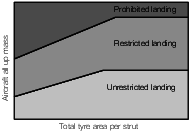
Figure 2.10.1 Landing diagrams
10.4.2 Normally,
for maximum flexibility in helicopter operations, the landing area
is to be taken as a square not less than 1,25 times the rotor diameter.
Where the operation of helicopters is restricted to known helicopter
types, the areas of deck structure to be assessed for the landing
condition are to be taken as squares not less than two times the maximum
wheel strut spacing. The squares are to be centred on all the normal
landing points, at all specified landing orientations, for all helicopters.
For fixed wing aircraft the area to be considered will be determined
by the operational requirements of the vessel. The landing area is
to be clearly identified.
10.4.3 The
takeoff and landing area are generally to be free of projections above
the level of the deck. Projections above 25 mm may only be permitted
where allowed by the aircraft undercarriage design standard. Projections
outside the landing and take off areas are to be kept to a minimum
such that they do not hinder aircraft manoeuvring operations.
10.4.4 The
structure is to be designed to accommodate the largest aircraft type
which it is intended to use. It is advised that an allowance be made
for future growth of the helicopter weight such that future operations
are not restricted to lower sea states.
10.4.5 Engine
uptake arrangements are to be sited such that exhaust gases cannot
as far as practicable be drawn directly into aircraft engine intakes
during aircraft take off or landing operations under anticipated operating
conditions that include ship speed, ship motion and wind direction.
10.4.6 Arrangements are to be made for the drainage of the flight deck and other aircraft
handling areas, including drainage of spilt fuel. The drainage arrangements are to be
made of steel and are to lead away from enclosed spaces and directly overboard so as to
avoid entrapment of burning fuel should an accident occur.
10.4.7 Flight decks are to be bounded by a coaming of approximately 50mm which is to be an
integral part of the drainage system.
10.4.8 Flight decks are to have at least two means of escape located as far away as practicable
from each other.
10.5 Loading
10.5.1 The load cases to be applied to all parts of the structure are defined in
Table 2.10.6 Design load cases for primary and
secondary deck stiffening and supporting structure in which:
|
f
|
= |
1,15
for landing decks over magazines or permanently manned spaces, e.g
deckhouses, bridges, control rooms, etc. |
| = |
1,0 elsewhere |
|
λ |
= |
reaction
factor for the aircraft considered . |
|
Wauw
|
= |
the maximum all up weight of the aircraft, in kN |
|
Wty
|
= |
landing or static load, on the tyre print, in kN; with the centre of
gravity in a position that causes the highest load. In the absence of specific
aircraft manufacturers’ information on the dynamic distribution of load,
Wty is to be taken as Wauw distributed
between all main undercarriages in accordance with the static load distribution.
The contribution of small nose or tail wheels is to be ignored. The structure only
needs to be assessed for the worst-case wheel loads and orientation. |
10.5.2 The
reaction factor, λ, may be determined from Table 2.10.1 Landing reaction factor where manufacturers’
information is not available. Otherwise the information in Vol 1, Pt 4, Ch 2, 10.6 Determination of λ for fixed wing aircraft or Vol 1, Pt 4, Ch 2, 10.7 Determination of λ for helicopters as appropriate may be used to estimate λ.
Table 2.10.1 Landing reaction factor
| Aircraft type
|
λ
|
| Helicopters
|
2,5
|
| VSTOL
aircraft
|
3,5
|
| Fixed
wing aircraft
|
5
|
Note Reaction factors are derived from the average values for
marinised versions of aircraft.
|
10.5.3 The
reaction factor for helicopters using recovery systems will be specially
considered.
10.6 Determination of λ for fixed wing aircraft
10.6.1 The
reaction factor can be calculated by simulation, testing or estimated
from the following formulae:
|
λ |
= |

|
where
|
λ |
= |
reaction
factor |
|
δS, δT |
= |
deflection
of the shock absorber or tyre, in metres |
|
V
L
|
= |
vertical landing velocity including ship motions, in m/s |
|
ηT |
= |
efficiency
of the tyre typically assumed to be 0,47 |
|
ηS |
= |
efficiency
of the shock absorber, see
Table 2.10.2 Shock absorber efficiency.
|
Table 2.10.2 Shock absorber efficiency
|
|
Steel spring
|
Rubber
|
Air
|
Liquid spring
|
OLEO
|
| η
|
0,5
|
0,6
|
0,48
|
0,76
|
0,8
|
10.6.2 The
vertical velocity is the maximum landing velocity derived from trials
or simulation and is to include the effects of ship motion. In no
case is it to be taken less than 6 m/s. If landing operations are
to be carried out in sea states greater than six then the minimum
vertical velocity will be further considered.
10.7 Determination of λ for helicopters
10.7.2 The
vertical velocity is the maximum landing velocity derived from ship
trials or simulation and is to include the effects of ship motion.
In no case is it to be taken less than 3,72 m/s. If landing operations
are to be carried out in sea states greater than six then the minimum
vertical velocity will be further considered.
10.7.3 For
ships where helicopter operations are restricted to sea states lower
than six the vertical velocities defined in Table 2.10.3 Vertical velocity can be used.
Table 2.10.3 Vertical velocity
| Sea state
|
Vertical velocity
|
| 6
|
3,72
|
| 5
|
3,35
|
| 4
|
2,97
|
| 3
|
2,60
|
| 2
|
2,23
|
10.7.4 Using
a vertical velocity lower than the design given in this section, for
example a land based helicopter, will result in higher probabilities
of exceedence. The derivation of vertical velocity is such that it
includes the effects of ship motions and pilot action and is independent
of the design vertical velocity of the undercarriage.
10.7.6 For
helicopters with skids, determination of the reaction factor will
be specially considered.
10.8 Deck plating design
10.8.1 The
deck plate thickness, t
p, within the landing
area is to be not less than:
|
t
p
|
= |
 mm mm
|
where
|
α |
= |
thickness
coefficient obtained from Figure 3.2.1 Tyre print chart using a value of β given by
|
|
β |
= |
tyre print
coefficient used in Figure 3.2.1 Tyre print chart
|
|
β |
= |
log10

|
|
k
s
|
= |
higher tensile steel factor defined in Vol 1, Pt 6, Ch 5 Structural Design Factors
|
|
s
|
= |
stiffener
spacing, in mm |
|
F
typ
|
= |
tyre force, in kN from Table 2.10.6 Design load cases for primary and
secondary deck stiffening and supporting structure
|
|
λ |
= |
reaction
factor for the aircraft considered, see
Vol 1, Pt 4, Ch 2, 10.5 Loading
|
|
γ |
= |
a location
factor given in Table 2.10.4 Location factor, γ
|
|
φ1, φ2 ,φ3
|
= |
are patch load correction factors determined
from Table 2.10.5 Patch load corrections
φ1, φ2, φ3
|
|
t
c
|
= |
permanent set correction in mm, see
Vol 1, Pt 4, Ch 2, 10.8 Deck plating design 10.8.2
|
|
a, s
|
= |
the panel dimensions in mm, see
Figure 2.10.2 Tyre patch dimensions
|
|
u, v
|
= |
the patch dimensions in mm, see
Figure 2.10.2 Tyre patch dimensions.
|
Table 2.10.4 Location factor, γ
| Location
|
Υ
|
| On decks
forming part of the hull girder
|
|
| (a) within
0,4L
R amidships
|
1,18
|
| (b) at the FP or
AP
|
1,0
|
|
|
Values for
intermediate locations are to be determined by interpolation
|
| Elsewhere
|
1,0
|
Table 2.10.5 Patch load corrections
φ1, φ2, φ3
| Factor
|
Condition
|
|
φ1
|
= |

|
|
v
1 = v, but ≤ s
u
1 = u, but ≤ a
|
|
φ2
|
= |
1,0 |
| = |

|
| = |
0,77a/u
|
|
for u ≤ (a –
s)
for a ≥u > (a –
s)
for u > a
|
|
φ3
|
= |
1,0 |
| = |
0,6 (s/v) + 0,4 |
| = |
1,2 (s/v) |
|
for v < s
for 1,5 > (v/s) > 1,0
for
(v/s) ≥ 1,5
|
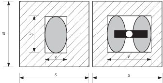
Figure 2.10.2 Tyre patch dimensions
10.8.2 The
permanent deflection correction, t
c, is a
plating thickness reduction which can be applied if aircraft manoeuvring
take off and deck equipment operations allow some permanent set to
occur
|
t
c
|
= |
0,001 mm mm
|
where
|
C
|
= |
0,00071
and n = 2,2 for moderate deformations
|
|
C
|
= |
0,0154
and n = 1,85 for large deformations.
|
10.8.3 Moderate
deformations are defined as those that will restrict manual manoeuvring
of the aircraft. They will typically be 1,5 times the deflection expected
from normal ship construction.
10.8.4 Large
deformations are defined as those that will restrict operations to
aircraft landing only with no wheeled vehicle operations they will
typically be 2,5 times the deflections expected from normal ship construction.
10.8.5 If
permanent deformation of the landing area plating is to be allowed
then the plating must also be assessed for normal operations with t
c = 0,0 mm.
10.8.6 The
permanent deflection correction is not to be applied to landing areas
within 0,3L
R to 0,7L
R and
other areas where there are significant in-plane stresses in the plate.
Also the correction is not to be applied to areas where deflections
could cause operational restrictions, for example the use of forklift
trucks or rolling take off.
10.8.7 The
static tyre print dimensions at W
auw specified
by the manufacturer are to be used for the calculation. Where these
are unknown it may be assumed that the print area is 200 mm x 300
mm and this assumption is to be indicated on the submitted plan.
10.8.9 For
helicopters fitted with landing gear consisting of skids, the print
dimensions specified by the manufacturer are to be used. Where these
are unknown it may be assumed that the print consists of a 300 mm
line load at each end of each skid, when applying Figure 3.2.1 Tyre print chart
10.8.11 For steel decks in frequent use and where no suitable protective sheathing
or coating is used, it is recommended that the thickness of the plating is increased,
see
Vol 1, Pt 6, Ch 6, 3.8 Corrosion margin
10.9 Deck stiffening design
10.9.2 The
minimum requirements for section modulus, inertia and web area of
secondary stiffeners are to be in accordance with the requirements
of Table 3.2.3 Secondary stiffener
requirements,
using the load cases defined in Table 2.10.6 Design load cases for primary and
secondary deck stiffening and supporting structure
Table 2.10.6 Design load cases for primary and
secondary deck stiffening and supporting structure
| Condition
|
Loading
|
Plate
Ftyp
kN
|
Stiffening
|
Support structure
|
Ptyw
kN/m2
|
Point loads Ftys
kN
|
Self weight
Ftym
kN
|
Vertical
kN
|
Horizontal
kN
|
| Emergency landing
|
λ f
Wty
|
0,2
|
DLF λ f
Wty
|
(1 +
a
z) Ws
|
Self weight
Wpl plus landing loads from all wheels
|
0,5
Wauw
0,5 W
auw + 0,5 Wpl
|
| Normal
landing
|
0,6 λ
Wty
|
0,5
|
0,6
DLF λ Wty
|
(1 +
az) Ws
|
| Take off
(fixed wing)
|
2,65
Wty
|
0,5
|
2,65
Wty
|
(1 +
az) Ws
|
| Manoeuvring
internal
|
1,6
Wty
|
—
|
1,6
Wty
|
(1 +
az) Ws
|
| Manoeuvring
external
|
1,75
Wty
|
0,5
|
1,75Wty
|
(1 +
az) Ws
|
| Parking
internal
|
(1 +
0,6az ) Wty
|
—
|
(1 +
0,6a
z) Wty
|
(1 +
a
z) Ws
|
| Parking
external
|
1,1(1 +
0,6az) Wty
|
2
|
1,1(1 +
0,6az) Wty
|
(1 +
az) Ws
|
Wty, Wauw and f as defined in
Vol 1, Pt 4, Ch 2, 10.5 Loading
λ is defined in Vol 1, Pt 4, Ch 2, 10.8 Deck plating design
|
Wpl
|
= |
structural weight of helicopter platform, in kN |
|
Ws
|
= |
structural weight of stiffener and supported
structure, in kN |
|
Ptyw
|
= |
uniformly distributed vertical load over entire
landing area, kN/m2
|
|
|
DLF
|
= |
Dynamic load factor |
a
z is defined in Vol 1, Pt 5, Ch 3, 2 Motion response
|
Fixed wing 1,35 for secondary stiffening, 1,5 for
primary stiffening
.
Helicopters 1,2 for
secondary stiffening, 1,5 for primary stiffening.
|
Note
1. For the design of the supporting
structure for helicopter platforms applicable self-weight and
horizontal loads are to be added to the landing area loads.
Note
2. The helicopter is to be so positioned
as to produce the most severe loading condition for each structural
member under consideration.
Note
3. Stiffening members may have more than
one point load acting at one time.
|
10.9.3 For
primary stiffening, and where a grillage arrangement is adopted, it
is recommended that direct calculation procedures are used to determine
the scantling requirements in association with the limiting permissible
stress criteria given in Table 5.3.2 Allowable stress factors f
1 in Pt 6, Ch 5. The calculation is to be submitted for
consideration.
10.10 Parking and manoeuvring areas
10.10.1 For
areas designed for parking and manoeuvring of aircraft the maximum
take off weight of the aircraft is to be used with the maximum fuel
and payload.
10.10.3 Parking
areas may not be taken less than two frame spaces or the tyre width
plus 500 mm whichever is the greater. Consideration should be given
to the use of removable lagging around these areas and at the adjacent
beam bulkhead connection.
10.10.4 Additional
forces from tie down arrangements on the structure need only be considered
if the tensioning force applied exceeds that imposed by the forces
from ship motions as defined in Vol 1, Pt 4, Ch 2, 10.14 Aircraft tie-downs.
10.10.5 Decks
subjected to a combination of parking and significant in-plane stresses
will be specially considered.
10.11 Assisted take off
10.11.1 Where
the aircraft jet is not parallel to the deck at the moment of launch
or jet blast deflectors are used the structure is to be capable of
withstanding the thermal loads imposed on the deck.
10.11.2 The
structure of ramps used to assist take off are to be specially considered.
10.11.3 Structure
surrounding catapults is to be effectively supported and designed
for the maximum forces imposed by the launch system using the stress
criteria given in Table 5.3.2 Allowable stress factors f
1 in
Pt 6, Ch 5.
10.12 Arrested landing
10.12.1 Structure
surrounding arresting gear is to be effectively supported and designed
for the maximum forces imposed by the arrested aircraft using the
stress criteria given in Table 5.3.2 Allowable stress factors f
1 in Pt 6, Ch 5.
10.13 Vertical recovery
10.13.1 The
structure in way of the landing area and approach path is to be capable
of withstanding the thermal loads imposed by hot exhaust gases.
10.14 Aircraft tie-downs
10.14.1 Aircraft tie-downs or general anchoring points are to be provided on the flight deck and
in hangar spaces and are to be flush with the deck, when not in use.
10.14.2 The forces to be used in assessing the tie-down points are to preferably be
determined with regards to specific aircraft but where the aircraft is unknown the
designer may propose reasonable assumptions. Consideration is to be given to the range
of angles of application of the force due to the relationship between the aircraft
undercarriage arrangement and the spacing and arrangement of the tie-down points.
10.14.3 Tie-down points are to be tested in accordance with a suitable testing regime agreed
with LR.
|