
Section
6 Construction details
6.1 Continuity and alignment
6.1.1 Continuity
is to be maintained where primary members intersect and where the
members are of the same depth, a suitable gusset plate or brackets
are to be fitted, see
Figure 6.6.1 Primary member intersection
6.1.2 The
toes of brackets, etc. are not to land on unstiffened panels of plating.
Special care is to be taken to avoid notch effects at the toes of
brackets, by making the toe concave or otherwise tapering it off.
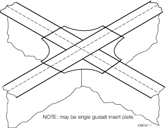
Figure 6.6.1 Primary member intersection
6.1.3 Particular
care is to be paid to the design of the end bracket toes in order
to minimise stress concentrations. Sniped face plates which are welded
onto the edge of primary member brackets are to be carried well around
the radiuses bracket toe and are to incorporate a taper not exceeding
one in three. Where sniped face plates are welded adjacent to the
edge of primary member brackets, adequate cross-sectional area is
to be provided through the bracket toe at the end of the snipe. In
general, this area measured perpendicular to the face plate, is to
be not less than 60 per cent of the full cross-sectional area of the
face plate, see
Figure 6.6.2 Bracket toe construction
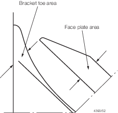
Figure 6.6.2 Bracket toe construction
6.2 Primary end connections
6.2.1 The
requirements for section modulus and inertia (if applicable) of primary
members are given in the appropriate Chapter. The scantling requirements
for primary member end connections in dry spaces and in tanks of all
ship types are generally to comply with the requirements of Vol 1, Pt 6, Ch 2 Design Tools,Vol 1, Pt 6, Ch 3 Scantling Determination,
taking Z as the section modulus of the primary member.
6.2.3 Connections
between primary members forming ring system are to minimise stress
concentrations at the junctions. Integral brackets are generally to
be radiused or well rounded at their toes. The arm length of the bracket,
measured from the face of the member, is to be not less than the depth
of the smaller member forming the connection.
6.2.4 The
requirements of this Section may be modified where direct calculation
procedures are adopted to analyse the stress distribution in the primary
structure.
6.2.6 The
minimum thickness or area of material in each component part of the
primary member is given in Table 6.6.1 Minimum thickness of primary
members.
Table 6.6.1 Minimum thickness of primary
members
| Item
|
Requirement
|
| (1)
|
Member web plate
(see Note)
|
tw = 0,01Sw
but not less than 6 mm in
dry
spaces
and not less than 7 mm in
tanks
|
| (2)
|
Member face plate
|
Af not to exceed  cm2 cm2
|
| (3)
|
Deck plating forming the upper flange of
underdeck girders
|
Plate thickness not less than
 mm mm
|
| Symbols
|
|
dw
|
= |
depth of member web, in mm |
|
tw
|
= |
thickness of member web, in mm |
|
Af
|
= |
area of member face plate or flange, in cm2
|
|
Sw
|
= |
spacing of stiffeners on member web, or depth of
unstiffened web, in mm |
|
Note For primary members having a web depth exceeding 1500 mm,
the arrangement of stiffeners will be individually considered, and
stiffening parallel to the member face plate may be required.
|
6.3 Secondary member end connections
6.3.1 Secondary
members, that is longitudinals, beams, frames and bulkhead stiffeners
forming part of the hull structure, are to be effectively continuous
and are to be suitably bracketed at their end connections. Where it
is desired to adopt bracketless connections, the proposed arrangements
will be individually considered, see also
Table 6.5.3 Connections of primary
structure.
6.3.2 Where
bracketed end connections are fitted in accordance with these requirements,
they may be taken into account in determining the effective span of
the member.
6.4 Scantlings of end brackets
6.4.1 For
a naval ship, longitudinal strength members are to be continuous through
primary supports. In exceptional cases for ships having a military
distinction notation MD and in areas not subject to significant
fatigue loading, longitudinal strength members may be cut at a primary
support and the continuity of strength is to be provided by brackets.
In such cases the scantlings of the brackets are to be such that their
section modulus and effective cross-sectional area are not less than
those of the member. Care is to be taken to ensure correct alignment
of the brackets on each side of the primary member.
6.4.2 In other
cases the scantlings of the bracket are to be based on the modulus
as follows:
-
Bracket connecting
stiffener to primary member – modulus of the stiffener.
-
Bracket at the
head of a main transverse frame where frame terminates – modulus
of the frame.
-
Brackets connecting
lower deck beams or longitudinals to the main frame in the forward
0,5L
R – modulus of the frame.
-
Elsewhere –
the lesser modulus of the members being connected by the bracket.
6.4.5 The
lengths, d
a and b
a,
of the arms are to be measured from the plating to the toe of the
bracket and are to be such that:
-
d
a + b
a ≥ 2,0lb
-
d
a ≥
0,8lb
-
b
a ≥
0,8lb
where
a and b are the
actual lengths of the two arms of the bracket, in mm, measured from
the plating to the toe of the bracket
|
lb
|
= |

|
|
Z
|
= |
the
section modulus of the secondary member, in cm3. In no
case is lb to be taken as less than twice the web
depth of the stiffener on which the bracket scantlings are to be based.
|
6.4.6 The
scantlings of deep web frames are based on the inclusion of the standard
brackets specified in Vol 1, Pt 6, Ch 6, 6.4 Scantlings of end brackets 6.4.5 at
top and bottom, while the scantlings of side frames are normally to
be based on a standard bracket at the top only. Where the actual arm
lengths fitted, d
a1, and b
a1 (in
mm) are smaller than Rule size above or the bracket is omitted then,
for comparison purposes, an equivalent arm length, la,
is to be derived from:
-

-
d
a1 ≥ 0,8la
-
b
a1 ≥ 0,8la
-
la =
0
where
-
bracket is omitted
from the upper or lower ends of the frame, or
-
lower frame
bracket at bilge is at same level as the inner bottom, or
-
lower frame
is welded directly to the inner bottom.
6.4.7 The
free edge of the bracket is to be stiffened where any of the following
apply:
-
The section modulus, Z, exceeds 2000 cm3.
-
The length of
free edge exceeds 50 times the bracket thickness.
-
The bracket is
fitted at the lower end of main transverse side framing.
6.4.8 Where
a face flat is fitted, its breadth, b
f, is
to be not less than:
6.4.9 Where
the edge is stiffened by a welded face flat, the cross-sectional area
of the face flat is to be not less than:
-
0,009k
s
b
f
t
b cm2 for
offset edge stiffening.
-
0,014k
s
b
f
t
b cm2 for
symmetrically placed stiffening.
|
b
f
|
= |
breadth of face flat, in mm |
6.4.10 Where
the stiffening member is lapped on to the bracket, the length of overlap
is to be adequate to provide for the required area of welding. In
general, the length of overlap is not to be less than  , or the depth of stiffener, whichever is the greater. , or the depth of stiffener, whichever is the greater.
6.4.11 Where
the free edge of the bracket is hollowed out, it is to be stiffened
or increased in size to ensure that the modulus of the bracket through
the throat is not less than that of the required straight edged bracket.
6.4.12 The
arrangement of the connection between the stiffener and the bracket
is to be such that at no point in the connection is the actual modulus
reduced to less than that of the stiffener with associated plating.
6.4.13 The
design of end connections and their supporting structure is to be
such as to provide adequate resistance to rotation and displacement
of the joint.
6.4.14 The
thickness of the bracket is to be not less than as required by Table 6.6.2 Thickness of end brackets.
Table 6.6.2 Thickness of end brackets
| Bracket
|
Thickness, in mm
|
LImits
|
| Minimum, in mm
|
Maximum, in mm
|
| With edge stiffened:
|
|
|
|
| (a)
|
in dry spaces
|
3,5 + 0,25
|
6,5
|
12,5
|
| (b)
|
in deep tanks
|
4,5 + 0,25
|
7,5
|
13,5
|
| Unstiffened brackets:
|
|
|
|
| (a)
|
in dry spaces
|

|
7,5
|
|
| (b)
|
in deep tanks
|

|
8,5
|
|
6.5 Arrangement at intersection of continuous
secondary and primary members
6.5.1 Lugs or tripping brackets are to be fitted where shell longitudinals are
continuous through web frames in way of highly stressed areas of the side shell (e.g. in
way of equipment supports, bollards, fenders, etc.).
6.5.2 Lugs or tripping brackets are also to be fitted where continuous secondary
stiffeners are greater than half the depth of the primary stiffeners.
6.5.5 The breadth of cut-outs is to be as small as practicable, with the top edge
suitably radiused. Cut-outs are to have smooth edges, and the corner radii are to be as
large as practicable. Where the web depth is greater than 100 mm the corner radii are to
be a minimum of 20 per cent of the breadth of the cut-out or 20 mm, whichever is the
greater, and for large cut-outs greater than 250 mm deep, the web plate connection to
the hull envelope, or bulkhead, should end in a smooth tapered ‘soft toe’. Recommended
shapes of cut-out are shown in Figure 6.6.4 Typical lug connections, but consideration will be given to other
shapes on the basis of maintaining equivalent strength and minimising stress
concentration.
6.5.6 Consideration is to be given to the provision of adequate drainage and
unimpeded flow of air and water when designing the cut-outs and connection details.
6.5.7 Asymmetrical secondary members are to be connected on the heel side to the
primary member web plate. Additional connection by lugs on the opposite side may be
required.
6.5.8 Symmetrical secondary members are to be connected by lugs on one or both
sides, as necessary.
6.5.9 Where a bracket is fitted to the primary member web plate in addition to a
connected stiffener it is to be arranged on the opposite side to, and in alignment with
the stiffener. The arm length of the bracket is to be not less than the depth of the
stiffener, and its cross-sectional area through the throat of the bracket is to be
included in the calculation of A
f, see
Vol 1, Pt 6, Ch 6, 5.13 Intersection of primary and secondary members 5.13.1.
6.5.10 In general where the primary member stiffener is connected to the secondary
member it is to be aligned with the web of the secondary member, except where the face
plate of the latter is offset and abutted to the web, in which case the stiffener
connection is to be lapped. Lapped connections of primary member stiffeners to mild
steel bulb plate or rolled angle secondary members may also be permitted. Where such
lapped connections are fitted, particular care is to be taken to ensure that the primary
member stiffener wrap around weld connection is free from undercut and notches.
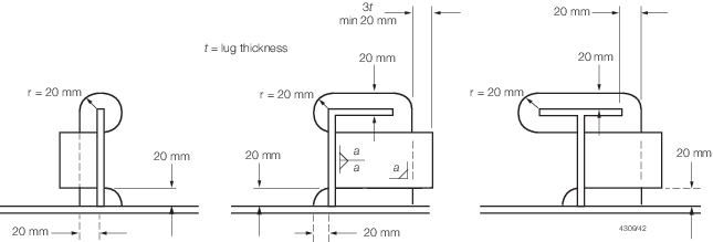
Figure 6.6.4 Typical lug connections

Figure 6.6.5 Cut-out and connections
6.5.11 Fabricated longitudinals having the face plate welded to the underside of
the web, leaving the edge of the web exposed, are not recommended for side shell and
longitudinal bulkhead longitudinals. Where it is proposed to fit such sections, a
symmetrical arrangement of connection to transverse members is to be incorporated. This
can be achieved by fitting backing brackets on the opposite side of the transverse web
or bulkhead. The primary member stiffener and backing brackets are to be lapped to the
longitudinal web, see
Vol 1, Pt 6, Ch 6, 6.5 Arrangement at intersection of continuous secondary and primary members 6.5.10.
6.5.12 The cross-sectional areas of the connections are to be determined from the
proportion of load transmitted through each component in association with the
appropriate allowable stress coefficient given in Table 6.6.3 Allowable stress
coefficients.
Table 6.6.3 Allowable stress
coefficients
| Item
|
Allowable direct stress
coefficient, f
σ (see Note 1)
|
Allowable shear
stress coefficient, f
τ(see Note 1)
|
| Primary web plate stiffener adjacent
to connection with secondary member
|
0,67
|
—
|
| Welded connection of primary member
web plate stiffener to secondary member:
|
|
|
| Double continuous fillet
|
0,50
|
—
|
| Automatic deep penetration
|
0,67
|
—
|
| Lug or collar plate and weld connection
|
—
|
0,72
(see Note
2)
|
|
Note 2. For emergency landing areas, the allowable shear stress
coefficient fτ is to be taken as 0,90.
|
6.5.13 The load transmitted through the intersection arrangement is to be
determined using the design pressure for the structural element being assessed in
accordance with Vol 1, Pt 5, Ch 3 Local Design Loads.
6.5.14 Total load, P, transmitted to the primary member from the secondary member is to
be derived by:
where
|
s |
= |
secondary stiffener spacing, mm |
|
S |
= |
primary stiffener spacing, m |
|
p |
= |
design plating pressure, kN/m2 |
|
P |
= |
total load, kN |
6.5.15 The arrangement of lug/collar/direct connection to the primary web
stiffener determines the load apportioned to each component. The effect on each
component of the intersection is to be assessed for shear and direct stress. Where the
web stiffener is not connected to the secondary member, the load, P, is
transmitted through the lug/collar/direct connection.
6.6 Arrangement with offset stiffener
6.6.1 Where
the stiffeners of the double bottom floors and transverse bulkheads
are unconnected to the secondary members and offset from them (see
Figure 6.6.6 Arrangement with offset stiffener) the collar arrangement
for the secondary members are to satisfy the requirements of Vol 1, Pt 6, Ch 6, 6.5 Arrangement at intersection of continuous secondary and primary members 6.5.4. In addition, the fillet welds
attaching the lugs to the secondary members are to be based on a weld
factor of 0,44 for the throat thickness. To facilitate access for
welding the offset stiffeners are to be located 50 mm from the slot
edge furthest from the web of the secondary member. The ends of the
offset stiffeners are to be suitably tapered and softened.
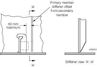
Figure 6.6.6 Arrangement with offset stiffener
6.6.2 Alternative
arrangements will be considered on the basis of their ability to transmit
load with equivalent effectiveness. Details of the calculations made
and testing procedures are to be submitted.
6.7 Watertight collars
6.7.1 Watertight
steel collars are to be fitted, where stiffeners are continuous through
watertight or oiltight boundaries.
6.7.2 Watertight
steel collars or equivalent are to be fitted at gastight boundary.
6.8 Insert plates
6.8.1 Where
thick insert plates are butt welded to thin plates, the edge of the
thick plate may require to be tapered. The slope of the taper is generally
not to exceed one in three.
6.8.2 The
corners of insert plates are generally to be suitably radiused.
6.9 Doubler plates
6.9.1 Doubler
plates are to be avoided and are not to be fitted in areas where corrosion
may be a problem and access for inspection and maintenance is limited.
6.9.2 Where
doubler plates are fitted, they are to have well radiused corners
and the perimeter is to be continuously welded. Large doubler plates
are also to be suitably slot welded, the details of which are to be
submitted for consideration.
6.10 Other fittings and attachments
6.10.1 Gutterway
bars and spurnwaters are not to be welded to boundary angles, or within
100 mm of the deck edge.
6.10.2 Minor
attachments, such as pipe clips, staging lugs and supports, are generally
to be kept clear of toes of end brackets, corners of openings and
similar areas of high stress. Where connected to asymmetrical stiffeners,
the attachments may be in line with the web providing the fillet weld
leg length is clear of the offset face plate or flange edge. Where
this cannot be achieved the attachments are to be connected to the
web, and in the case of flanged stiffeners they are to be kept at
least 25 mm clear of the flange edge. On symmetrical stiffeners, they
may be connected to the web or to the centreline of the face plate
in line with the web.
6.10.3 Where
necessary in the construction of the ship, lifting lugs may be welded
to the hull plating but they are not to be slotted through.
6.11 Bilge keels and ground bars
6.11.1 Bilge
keel plating is to be attached to the shell plating as shown in Figure 6.6.7 Double plate bilge keel construction. Butt and seam welds
in shell plating and bilge keels are to be staggered by at least 100
mm.
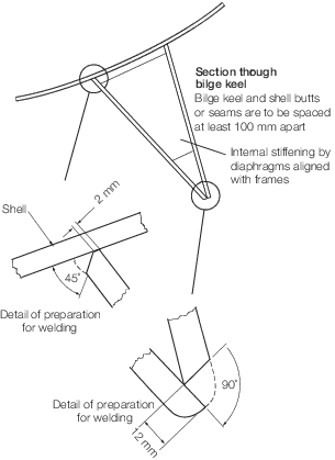
Figure 6.6.7 Double plate bilge keel construction
6.11.2 The
shell plating in way of the bilge keel is to be at least grade D.
Insert plates of 50 per cent greater thickness than the as fitted
surrounding shell plate are to be fitted. They are to be greater than
300 x 300mm2 with well rounded corners.
6.11.3 The
thickness of the bilge keel is to be assessed using the appropriate
scantling equation for shell envelope plating. To prevent possible
damage to the shell, the bilge keel plate is not to be thicker than
the adjacent shell plate. The material class, grade and quality of
the bilge keel plating is to be the same as the adjacent shell plating, see
Table 6.2.1 Material classes and
grades.
6.11.4 Full
continuous welding is to be used to connect the bilge keel to the
shell.
6.11.5 The
ends of the bilge keels are to have a 1 in 3 taper and terminate within
300 mm to 100 mm past an internal frame. Suitable internal framing
is to be arranged in way of the ends of the bilge keels where, for
hydrodynamic reasons, a steeper taper is necessary, the termination
of the bilge keels will be especially considered.
6.11.6 For
ships over 65 m in length, all welds are to be subject to non-destructive
examination.
6.11.8 Internal
stiffening is to be arranged in line with hull framing but is not
to be attached to the shell plating.
6.11.10 The
internal surfaces of the bilge keel and stiffening are to be suitably
protected against corrosion.
6.12 Rivetting of light structure
6.12.1 Where
it is proposed to adopt rivetted construction, full details of the
rivets or similar fastenings, including mechanical test results, are
to be indicated on the construction plans submitted for approval or
a separate rivetting schedule is to be submitted.
6.12.2 Samples
may be required of typical rivetted joints made by the Builder under
representative construction conditions and tested to destruction in
the presence of the Surveyor in shear, tension, compression or peel
at LR’s discretion.
6.12.3 Where
rivetting strength data sheets have been issued by a recognised Authority,
the values quoted in these sheets will normally be accepted for design
purposes.
6.12.4 Where
two dissimilar metals are to be joined by rivetting, precautions are
to be taken to eliminate electrolytic corrosion to LR’s satisfaction,
and where practicable, the arrangements are to be such as to enable
the joint to be kept under observation at each survey without undue
removal of lining and other items.
6.12.5 Where
a sealing compound is used to obtain an airtight or watertight joint,
details are to be submitted of its proposed use and of any tests made
or experience gained in its use for similar applications.
6.12.6 Sealing
paints or compounds are not to be used with hot driven rivets.
6.13 Adhesive bonding of structure
6.13.1 Where
adhesive bonding of any load-bearing structure is proposed, details
of the materials and the processes to be used are to be submitted
for approval. These details are to include test results of samples
manufactured under LR survey under workshop conditions to verify the
strength, ageing effects and moisture resistance of a typical joint.
6.13.2 The
adhesive manufacturer’s recommendations in respect of the specified
jointing system, comprising preparation of the surfaces to be adhered,
the adhesive, bonding and curing processes, are to be strictly followed
as variation of any step can severely affect the performance of the
joint.
6.13.3 Meticulous
preparation is essential where the joint is to be made by chemical
bonding. The method of producing bonded joints is to be documented
so that the process is repeatable after the procedure has been properly
established.
6.13.4 Bonded
joints are suitable for carrying shear loads, but are not, in general,
to be used in tension or where the load causes peeling or other forces
tending to open the joint. Loads are to be carried over as large an
area as possible.
6.13.5 Bonded
joints are to be suitably supported after assembly for the period
necessary to allow the optimum bond strength of the adhesive to be
developed. Air pockets are to be avoided.
6.13.6 The
use of adhesive for main structural joints is not to be contemplated
unless considerable testing has established its validity, including
environmental testing and fatigue testing where considered necessary
by LR.
6.14 Triaxial stress considerations
6.14.1 Particular
care is to be taken to avoid triaxial stresses which may result from
poor joint design.
6.15 Aluminium/steel transition joints
6.15.1 Provision
is made in this Section for bi-metallic composite aluminium/steel
transition joints used for connecting aluminium structures to steel
plating. Such joints are to be used in accordance with the manufacturer’s
requirements, see also
Ch 8, 4 Aluminium/steel transition joints of
the Rules for Materials.
6.15.2 Where
a manufacturer is not approved, details of the materials to be used
and the manufacturing procedures are to be submitted for approval
before use.
6.15.3 Bimetallic
joints where exposed to seawater or used internally within wet spaces
are to be suitably protected to prevent galvanic corrosion.
6.15.4 Control
of heat input is required when welding the transition joints to the
steel structure in order to prevent disbondment.
6.16 Steel/wood connection
6.16.1 To
minimise corrosion of steel when in contact with wood in a damp or
marine environment the timber is to be primed and painted in accordance
with good practice. Alternatively the surface of the steel in contact
with the timber is to be coated with a substantial thickness of a
suitable sealant.
|