
Section
4 Fragmentation protection
4.1 General
4.1.1 This
section does not deal with the loss of structural strength due to
material perforation. It is only concerned with fragmentation protection
of equipment and personnel within critical compartments and potentially
critical pipe and cable runs.
4.1.2 Fragment
and small arms penetrators can be stopped by the use of structure
designed to prevent penetration, either through the use of increased
thickness of normal structural materials, suitable siting of compartments,
addition of armour (non-structural) materials, or even the use of
armour material that can take structural loads.
4.1.3 The
Rules give design data based on fragment penetration equations for
three representative threats. The selection and use of fragment penetration
equations or computer modelling for other threats will be considered
provided they are carried out by a competent body which has relevant
experience and employs recognised procedures.
4.1.4 For
fragmentation protection to be effective, materials within the ship
forming part of the ship’s equipment and outfit shall be of
a type that is not prone to the generation of secondary fragments
or ‘splinters’. Materials such as wood, brittle plastics
and brittle cast materials are not to be used in protected compartments.
Where the use of such materials is essential, consideration may be
given to the use of bonded splinter-retaining membranes.
4.1.5 RATTAM
is defined as the response to attack on ammunition and describes protection
fitted externally to the ship to prevent the penetration of particular
threats which may cause damage, principally to magazines. Similar
protection may also be fitted to protect other critical compartments,
both are covered by the SP notation.
4.2 Threat level determination
4.2.1 The
threat may be classified as either small arms fire or fragments from
the casing of shells or warheads (‘shrapnel’ or ‘splinters’)
capable of perforating the ship's structure and thus causing damage
to equipment or casualties amongst personnel.
4.2.3 The
actual threat level and type used in the calculation and the areas
of the ship to be protected are to be specified by the Owner and will
remain confidential to LR.
Table 2.4.1 Fragment threat types
| Level
|
Typical threat origin
|
Fragment weight (g)
|
Initial fragment velocity
(m/s)
|
|
I
|
Aircraft fired 30 mm high explosive (HE) cannon
shell
|
up to 1 g
|
less than 1250
|
|
II
|
Proximity detonating 105 mm Artillery
round
|
up to 15 g
|
less than 1250
|
|
III
|
Sea Skimming (SAP) missile
|
up to 55 g
|
less than 1400
|
4.2.4 The
Level I threat is assumed to detonate on impact with the ship’s
structure in the act of which it will penetrate the outer skin of
the vessel. Fragmentation protection will reduce the risk of fragments
penetrating additional compartments. The ends, internal sides and
decks of critical compartments are in general to be fitted with protection,
an example of which is shown in Figure 2.4.1 Level I arrangement, see also
Vol 1, Pt 4, Ch 2, 4.3 Notation assessment levels and methodology 4.3.2. The outer skin of the ship may be strengthened to resist
the shell in accordance with the requirements for the SP notation,
however it will usually require a significant amount of armour.
4.2.6 The
Level III threat is a generic weapon based on a sea skimming anti-ship
weapon with a semi armour piercing, (SAP) warhead that detonates within
the hull. Fragmentation protection is intended to reduce the risk
of fragments penetrating additional compartments. The considerable
amount of protection required will normally mean that protection is
only fitted at zone boundaries to limit the longitudinal spread of
fragments. See example in Figure 2.4.3 Level III arrangement and also Vol 1, Pt 4, Ch 2, 4.3 Notation assessment levels and methodology 4.3.2.
4.3 Notation assessment levels and methodology
4.3.1 The
fragmentation protection FP1 and FP2 notations
are assigned for ships which have protection fitted to resist fragments
from the casing of a shell or warhead. The small arms protection, SP notation is assigned for ships fitted with protection to resist
the penetration of small arms fire into the hull. For ships where
the fragmentation resistance is carried out using the Tables and graphs
of this section an FP1 notation is assigned. Where fragmentation
testing or analysis is used to determine the fragmentation resistance
required a FP2 notation is assigned.
4.3.2 The
pressure produced by a Level I threat is such that an IB notation is not required. The Level II threat
is external and of a level such that an EB notation will
not be required. A Level III threat will require the
effect of the internal blast pressure on the structure to be considered
and IB and RSA notations will generally
be required.
4.4 Information required
4.4.1 For
each threat level it will be necessary to identify the critical compartments
requiring protection, plus the critical pipe and cable runs where
appropriate. Plans are to be provided showing the location and manner
of all fragmentation and terrorist attack protection.
4.4.2 Where
alternative tests or calculations have been carried out full details
are to be submitted. They are to include details of the organisation
involved, their experience, test or calculation procedures and the
program or equations used.
4.5 Structural requirements
4.5.1 Where
different threats, materials or multiple plate arrays are fitted alternative
methods may be used to determine the fragmentation resistance, for
example:
- Penetration equations.
- Finite element and fluid-codes.
- Experimental methods.
Ascending the levels of calculation complexity is not simply
a matter of increased cost in design, the increased complexity potentially
offers the reward of reduced protection requirement for the given
threats.
4.5.2 Armour
spaced normal to the threat can reduce the total thickness by up to
30 per cent. It may also be effective for bullets provided the gap
between plates is greater than 1,0 m.
4.5.4 For
Level II fragmentation protection, the equivalent thickness
of steel is to be determined from Figure 2.4.4 Level II fragmentation protection.
Table 2.4.2 Level I fragmentation
protection
| Material yield strength
N/mm2
|
Transverse bulkhead or deck
thickness mm
|
Longitudinal bulkhead thickness
mm
|
| 235
|
6,5
|
6,0
|
| 355
|
6,0
|
5,5
|
| 550
|
5,5
|
5,0
|
| RHA
|
5,0
|
4,5
|
Note RHA is defined as rolled homogenous armour.
|
4.5.5 For
Level III fragmentation protection, the equivalent thickness
of steel is to be determined from Figure 2.4.5 Level III fragmentation protection. Protection will normally be required to be provided
by several bulkheads or specific armour and the graph can serve only
as a guide. The structural protection for this type of threat will
generally be specially considered based on the particular weapon characteristics
and protection arrangements. It should also be noted that many modern
missiles generate controlled fragments which will need special consideration.
4.5.6 The
graphs are produced based on a 50 per cent probability of perforation
for penetrators perpendicular to the target.
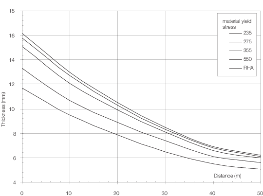
Figure 2.4.4 Level II fragmentation protection
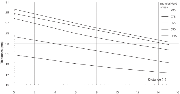
Figure 2.4.5 Level III fragmentation protection
|
| Copyright 2022 Clasifications Register Group Limited, International Maritime Organization, International Labour Organization or Maritime
and Coastguard Agency. All rights reserved. Clasifications Register Group Limited, its affiliates and subsidiaries and their respective
officers, employees or agents are, individually and collectively, referred to in this clause as 'Clasifications Register'. Clasifications
Register assumes no responsibility and shall not be liable to any person for any loss, damage or expense caused by reliance
on the information or advice in this document or howsoever provided, unless that person has signed a contract with the relevant
Clasifications Register entity for the provision of this information or advice and in that case any responsibility or liability is
exclusively on the terms and conditions set out in that contract.
|
 |
|