
Section
3 Main hull structure
3.1 General
3.1.1 The
Rules are formulated to provide for scantling derivation for designs
comprising the following structural framing systems. Details of the
requirements are given in Vol 1, Pt 6, Ch 2 Design Tools.
-
Primary/secondary
stiffener systems - where, due to the relative differences in stiffness
of the members, the secondary members are considered to act independently
of, and are supported by, the primary members.
-
Grillage systems
- where the relative stiffness of the orthogonal stiffening is similar
and work together to support the applied loads. The grillage system
is in turn supported by major structural members such as bulkheads
or decks.
3.1.3 For
practical reasons of fabrication and continuity of structure, orthogonal
systems using members of the same depth should not be employed. A
minimum web depth difference of 40 mm is generally to be used to allow
for the passage through the web at the intersections.
3.1.4 It is
recognised that there will be a reduction in transverse ‘racking’
strength in association with the grillage stiffening system where
the predominantly stiffer transverse web of the primary/secondary
system is missing. In large areas of grillage systems the ‘racking’
strength, therefore, will be specially considered.
3.1.5 For
NS1 and NS2 ships, longitudinal framing, in general, is to be adopted
in the bottom shell, decks and inner bottom, with transverse or longitudinal
framing at the side shell and longitudinal bulkheads. In NS3 ships,
transverse or longitudinal framing may be universally adopted.
3.1.6 The
adopted framing system whether longitudinal or transverse is required
to be continuous. Where it is impracticable to comply with these requirements
or where it is proposed to terminate the framing structure in way
of other primary members such as the transom, bulkheads or integral
tank boundaries, they are to be bracketed in way of their end connections
to maintain the continuity of structural strength. Particular care
is to be taken to ensure accurate alignment of the brackets. Brackets
are in general to have soft toes and to terminate on structure that
is capable of supporting the transmitted bending moment and forces.
3.1.7 The
arrangement of the connection between any stiffener and bracket is
to be such that at no point in the connection are the section modulus
and inertia reduced to less than that of the stiffener with associated
plating.
3.1.8 The
arrangement of material is to be such as will ensure structural continuity.
Abrupt changes of shape or section, sharp corners and points of stress
concentration are to be avoided.
3.1.9 Where
members abut on both sides of a bulkhead or similar structure, care
is to be taken to ensure good alignment and continuity of strength.
3.1.10 The
fitting of pillar bulkheads is preferable to pillars. The fitting
of pillars is to be avoided in hangar and vehicle decks and where
connected to the inner bottom. Where enhanced shock and blast requirements
are specified, only pillar bulkheads may be fitted. When fitted, pillars
and pillar bulkheads are to be in the same vertical line wherever
possible, and elsewhere arrangements are to be made to transmit the
out of line forces satisfactorily. The load at head and heel of pillars
is to be effectively distributed and arrangements are to be made to
ensure the adequacy and lateral stability of the supporting members.
3.1.11 End
connections of structural members are to provide adequate end fixity
and effective distribution of the load into the supporting structure.
3.1.12 The
corners of large openings in the shell and decks from 0,25L
R to 0,75L
R are to be elliptical, parabolic
or circular. Where predominantly unidirectional stress fields are
anticipated, elliptical or parabolic corners are recommended. Where
biaxial or torsional stress fields are expected, circular corners
are recommended.
3.1.13 Where
elliptical corners are arranged the major axis is to be fore and aft,
the ratio of the major to minor axis is to be not less than 2 to 1
nor greater than 2,5 to 1, and the minimum half-length of the major
axis is to be defined by l
1 in Figure 2.3.1 Opening geometry Where parabolic corners
are arranged, the dimensions are also to be as shown in Figure 2.3.1 Opening geometry. An increase in plate
thickness will not generally be required.
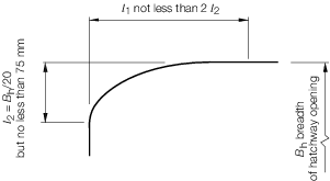
Figure 2.3.1 Opening geometry
3.1.14 Where
circular corners are arranged, a radius not less than 1/20 of the
breadth of the opening is to be used with a minimum of 75 mm. For
circular corners, inserts of the size and extent shown in Figure 2.3.2 Inserts in way of openings will, in general, be
required. The thickness of insert plates is to be not less than 25
per cent greater than the adjacent plating with a minimum increase
of 4 mm. The increase need not exceed 7 mm.
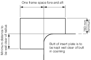
Figure 2.3.2 Inserts in way of openings
3.1.16 Manholes,
lightening holes and other cut-outs are to be avoided in way of concentrated
loads and areas of high shear. In particular, manholes and similar
openings are not to be cut in vertical or horizontal diaphragm plates
in narrow cofferdams or in floors and double bottom girders close
to their span ends, or below the heels of pillars, unless the stresses
in the plating and the panel buckling characteristics have been calculated
and found satisfactory. The sizes of openings are to be in accordance
with Vol 1, Pt 3, Ch 2, 3.2 Primary members 3.2.9.
3.1.17 Manholes,
lightening holes and other openings are to be suitably framed and
stiffened where necessary.
3.1.18 Provision
is made for the free passage of air and water taking into account
the pumping rates required.
3.1.19 Particular
care is to be given to the positioning of drain holes to reduce stress
concentrations and ensure adequate drainage from all parts of the
ship’s hull to the suctions. They are to be placed as close
to the bottom as practicable.
3.1.20 Suitable
arrangements are to be made to provide free passage of air from all
parts of tanks to the air pipes. They are to be placed as close to
the top of the tank as practicable. Air pipes of sufficient number
and area are to be fitted to each tank in accordance with Vol 1, Pt 3, Ch 4, 7 Air and sounding pipes.
3.1.21 Air
and drain holes, notches and scallops are to be kept at least 200
mm clear of the toes of end brackets and other areas of high stress.
Openings are to be well rounded with smooth edges. Closely spaced
scallops are not permitted.
3.1.22 Widely
spaced air or drain holes, cut entirely in the web adjacent to, but
clear of the welded connection, may be accepted, provided that they
are of elliptical shape, or equivalent, to minimise stress concentrations, see
Figure 2.3.3 Air/Drain hole geometry
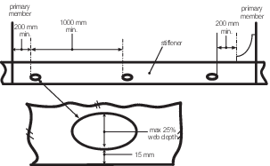
Figure 2.3.3 Air/Drain hole geometry
3.2 Primary members
3.2.2 Primary
members are to be so arranged as to ensure effective continuity of
strength, and abrupt changes of depth or section are to be avoided.
Where members abut on both sides of a bulkhead, or on other members,
arrangements are to be made to ensure that they are in alignment.
Primary members are to form a continuous line of support and, wherever
possible, a complete ring system.
3.2.3 Primary
members are to have adequate lateral stability and web stiffening
and the stiffening structure is to be arranged to minimise hard spots
and other sources of stress concentration.
3.2.4 Primary
members are to be provided with adequate end fixity by end brackets
or equivalent structure. The design of end connections and their supporting
structure is to be such as to provide adequate resistance to rotation
and displacement of the joint and effective distribution of the load
from the member. Where a deck girder or transverse is connected to
a vertical member on the shell or bulkhead, the scantlings of the
latter may be required to be increased to provide adequate stiffness
to resist rotation of the joint.
3.2.5 Where
the primary member is supported by structure which provides only a
low degree of restraint against rotation, the member is generally
to be extended beyond the point of support and thereafter tapered
and/or scarfed into the adjacent structure over a distance generally
not less than two frame spaces.
3.2.6 Where
primary members are subject to concentrated loads, particularly if
these loads are out of line with the member web, additional strengthening
may be required.
3.2.7 Where
a member is continued over a point of support, such as a pillar or
pillar bulkhead stiffener, the design of the end connection is to
be such as to ensure the effective distribution of the load into the
support. Brackets are generally required but alternative arrangements
will be considered.
3.2.8 The
thickness of the brackets supporting primary members is to be not
less than that of the primary member web. The free edge of the bracket
is to be stiffened.
3.2.9 Where
openings are cut in the web or primary members, the depth of opening
is not to exceed 50 per cent of the web depth, and the opening is
to be so located that the edges are not less than 25 per cent of the
web depth from the face plate. The length of opening is not to exceed
the web depth or 60 per cent of the secondary member spacing, whichever
is the greater, and the ends of the openings are to be equidistant
from the corners of cut-outs for secondary members. Where larger openings
are proposed, the arrangements and compensation required will be specially
considered.
3.2.10 Openings
are to have well rounded corners and smooth edges and are to be located
having regard to the stress distribution and buckling strength of
the panel in which they are situated.
3.2.11 Cut-outs
for the passage of secondary members are to be designed to minimise
the creation of stress concentrations. The breadth of cut-out is to
be kept as small as practicable and the top edge is to be rounded,
or the corner radii made as large as practicable. The extent of the
direct connection to the web plating, or the scantlings of lugs or
collars, is to be sufficient for the loads to be transmitted from
the secondary member, see also
Vol 1, Pt 6, Ch 6, 6.5 Arrangement at intersection of continuous secondary and primary members
3.3 Shell plating
3.3.2 The
sheerstrake is generally to be taken as the side shell, locally reinforced
in way of deck/hull connection. The amount of local reinforcement
will be dependent upon the arrangement of structure and the proposed
service.
3.3.3 In general,
openings are not to be cut in the sheerstrake; however, if operational
requirements dictate, openings that are less than 20 per cent of the
depth of the sheerstrake may be accepted. Openings greater than 20
per cent of the depth of the sheerstrake will require special consideration.
3.3.4 Where
large side shell openings, such as side aircraft lifts, are proposed,
detailed calculations are to be submitted.
3.3.5 Where
rounded gunwales are fitted, arrangements are to ensure a smooth transition
from rounded gunwale to angled gunwale.
3.3.6 At the
ends of superstructures where the side plating is extended and tapered
to align with the bulwark plating, the transition plating is to be
suitably stiffened and supported. Where freeing ports or other openings
are essential in this plate, they are to be suitably framed and kept
well clear of the free edge.
3.3.7 Sea-inlets,
or other openings, are to have well rounded corners and, so far as
is practicable, are to be kept clear of the bilge radius, chine or
radiused sheerstrake. Arrangements are to be made to maintain the
strength in way of the openings. Additional thickness is to be required
in accordance with Vol 1, Pt 6, Ch 3, 5.7 Sea inlet boxes.
Adequate provision is to be taken to prevent local resonance problems.
Additional guidance for the design of sea-inlets or other openings,
is given in Vol 1, Pt 4, Ch 1, 8 Design guidance for the reduction of radiated noise underwater due to sea inlets or other openings.
3.3.8 Openings
on or near the bilge radius may be accepted provided that they are
of elliptical shape, or equivalent, to minimise stress concentrations
and are, in general, to be kept clear of weld connections.
3.3.9 The
scantlings of appendages (e.g. ‘A’ brackets) are covered
in Vol 1, Pt 3, Ch 3 Ship Control Systems. However, in way of
the hull penetrations, particular care will be required to be given
to the strength and watertight integrity of the shell.
3.4 Shell framing
3.4.2 Longitudinal
framing is, in general, to be adopted in the bottom, but special consideration
will be given to proposals for transverse framing in this region, see
Vol 1, Pt 3, Ch 2, 3.1 General 3.1.5
3.4.3 For
NS1 and NS2 ships, the bottom and side longitudinals are to be continuous
in way of both watertight and non-watertight floors, but equivalent
arrangements will be specially considered.
3.4.4 Bottom
and side longitudinals are to be supported by primary transverse structure
such as bottom transverses, floors or bulkheads, generally spaced
not more than 2,5 m apart in NS1 and NS2 ships, and 1,5 m in NS3 ships.
3.4.5 Bottom
and side transverses, where fitted, are to be continuous and substantially
bracketed at their end connections to side and deck transverses and
bottom floors.
3.4.6 Bottom
and side frames are to be effectively continuous and bracketed at
their end connections to side frames, deck beams and bottom floors
as appropriate. Side frames are to be supported by decks or stringers
spaced not more than three metres apart.
3.4.7 Bottom
girders and side stringers supporting transverse frames are to be
continuous through transverse bulkheads and supporting structures.
They are to be supported by deep transverse web frames, floors, bulkheads,
or other primary structure, generally spaced not more than three metres
apart.
3.4.11 Where
the shell framing is of unusual design or proportions, the scantlings
are to be determined by direct calculation.
3.5 Single bottom structure
3.5.2 The
requirements of this section provide for single bottom construction
in association with transverse and longitudinal framing systems, see
Vol 1, Pt 3, Ch 2, 3.1 General 3.1.5
3.5.3 All
girders are to extend as far forward and aft as necessary and care
is to be taken to avoid any abrupt discontinuities. Where girders
are cut at bulkheads, alignment and longitudinal strength are to be
maintained.
3.5.4 Particular
care is to be taken to ensure that the continuity of structural strength
in way of the intersection of transverse floors and longitudinal girders
is maintained. The face flats of such stiffening members are to be
effectively connected.
3.5.6 A continuous
centreline girder is, in general, to be fitted in all ships throughout
the length of the hull as far forward and aft as practicable.
3.5.7 Where
the floor breadth at the upper edge exceeds 6,0 m, side girders are
to be fitted at each side of the centre girder such that the spacing
between the side and centre girders or between the side girders themselves
is not greater than 3 m. In general, side girders where fitted are
to be continuous, extend as far forward and aft as practicable and
to terminate in way of bulkheads, deep floors or other primary transverse
structure. In addition, continuous intercostal longitudinal stiffeners
are to be fitted where the panel size exceeds the ratio 4 to 1.
3.5.8 In ships
with a transversely framed bottom construction, the bottom shell plating
is, in general, to be reinforced with additional continuous, or intercostal,
longitudinal stiffeners. Alternative arrangements to be considered.
3.5.10 In
longitudinally framed ships, plate floors are to be fitted as given
in Vol 1, Pt 3, Ch 2, 3.4 Shell framing 3.4.4. The connections
with side transverse web frames are to be as required by Vol 1, Pt 3, Ch 2, 3.4 Shell framing 3.4.6. Additional transverse floors
or webs are in general to be fitted at the half spacing of primary
transverse structure in way of engine seatings, thrust bearings, pillars,
skegs, bilge keels and the bottom of the ship forward.
3.5.11 The
tops of the floors may be level from side to side. However, in ships
having considerable rise of floor the depth of floors may require
to be increased to maintain the required section modulus.
3.5.12 In general, the floors in way of the sterntubes, shaft brackets, etc. are
to provide effective support for these items.
3.6 Double bottom structure
3.6.2 Double
bottoms are in general to be fitted in NS1 ships and are to extend
from the collision bulkhead to the aft peak bulkhead, as far as this
is practicable within the design and proper working of the ship. The
specified subdivision and stability standard may contain additional
requirements for the height and extent of the double bottom.
3.6.3 A double
bottom is generally not required in way of watertight compartments
used exclusively for the carriage of liquids, provided the safety
of the ship in the event of bottom damage is not thereby impaired.
Suitable scarfing arrangements are to be made to maintain continuity
of the inner bottom.
3.6.4 The
inner bottom is to be continued to the ship’s side as far as
practicable, in such a manner as to protect the bottom to the turn
of bilge or chine.
3.6.5 The
centreline girder and side girders are to extend as far forward and
aft as practicable and care is to be taken to avoid any abrupt discontinuities.
Where girders are cut at bulkheads, their alignment and longitudinal
strength are to be maintained.
3.6.6 Small
wells constructed in the double bottom structure are not to extend
in depth more than necessary. A well extending to the outer bottom
may, however, be permitted at the after end of the shaft tunnel of
the ship. Other well arrangements (e.g. for lubricating oil under
main engines) may also be considered provided they give protection
equivalent to that afforded by the double bottom.
3.6.7 Sufficient
manholes are to be cut in the inner bottom, floors and side girders
to provide adequate access to, and ventilation of, all parts of the
double bottom. Openings are to be in accordance with Vol 1, Pt 3, Ch 2, 3.2 Primary members 3.2.9
3.6.8 The
number and position of manholes are to be such that access under service
conditions is neither difficult nor dangerous.
3.6.9 Manholes
and their covers are to be of an approved design or in accordance
with a recognised National or International Standard.
3.6.10 Provision
is to be made for the free passage of air and water from all parts
of the tanks to the air pipes and suctions, account being taken of
the pumping rates required.
3.6.11 Adequate
access is also to be provided to all parts of the double bottom for
future maintenance, surveys and repairs. The edges of all openings
are to be smooth.
3.6.12 A
plan showing the location of manholes and access openings within the
double bottoms is to be submitted.
3.6.15 The
Rules are formed on the basis that access to double bottoms will be
by means of manholes with bolted covers. However, alternative arrangements
will be specially considered.
3.6.16 In
way of ends of floors and girders and transverse bulkheads, the number
and size of holes are to be kept to a minimum, the openings are to
be circular or elliptical and edge stiffening may be required.
3.6.17 Holes
are not to be cut in the centre girder, except in tanks at the forward
and after ends of the ship or where tank widths are reduced unless
additional stiffening and/or compensation is fitted to maintain the
structural integrity.
3.6.18 Centreline
and side girders are to be continuous and sufficient to withstand
the forces imposed by dry-docking the ship, see
Vol 1, Pt 4 Military Design and Special Features. Vertical stiffeners are to be fitted
at every bracket floor.
3.6.19 Where
the breadth of floor is greater than 6,0 m, additional side girders
having the same thickness as the floors are to be fitted. The number
of side girders is to be such that the distance between the side girders
and centre girder and margin plate, or between the side girders themselves,
does not exceed 3,0 m (for transversely framed ships, 5,0 m for longitudinally
framed ships).
3.6.20 Side
girders where fitted are to extend as far forward and aft as practicable
and are in general to terminate in way of bulkheads, deep floors or
other primary transverse structure.
3.6.21 Plate
floors are, in general, to be continuous between the centre girder
and the margin plate. Vertical stiffeners are to be fitted to the
floors, the number and positions of these stiffeners being dependent
on the arrangement of the double bottom structure.
3.6.22 In
longitudinally framed ships, plate floors or equivalent structure
are, in general, to be fitted in accordance with Vol 1, Pt 3, Ch 2, 3.4 Shell framing 3.4.4 and additionally at the following
positions:
-
At every half
spacing of primary transverse structure as given in Vol 1, Pt 3, Ch 2, 3.4 Shell framing 3.4.4, in way of the bottom of the
ship forward of 0,8L
R.
-
Underneath pillars
and bulkheads.
3.6.23 In
transversely framed NS3 ships, plate floors are to be fitted at every
frame in the engine room, under bulkheads, in way of change in depth
of double bottom and elsewhere at a spacing not exceeding 1,5 m.
3.6.24 Between
plate floors, the shell and inner bottom are to be supported by bracket
floors. The brackets are to have the same thickness as plate floors
and are to be stiffened on the unsupported edge.
3.6.25 In
longitudinally framed ships, the bracket floors are to extend from
the centre girder and margin plate to the adjacent longitudinal, but
in no case is the breadth of the bracket floor to be taken as less
than 75 per cent of the depth of the centre girder. They are to be
fitted at every frame at the margin plate, and those at the centre
girder are to be spaced not more than 1,0 m apart.
3.6.26 In
transversely framed ships, the breadth of the bracket floors, attaching
the bottom and inner bottom frames to the centre girder and margin
plate, is to be not less than 75 per cent of the depth of the centre
girder, see
Figure 1.5.5 Transverse framing system.
3.6.27 Inner
bottom longitudinals are to be supported by inner bottom transverses,
floors, bulkheads or other primary structure, generally spaced not
more than 2,5 m apart in NS1 and NS2 ships, and 1,5 m in NS3 ships.
3.6.28 The
inner bottom longitudinals are to be continuous through the supporting
structure.
3.6.29 Inner
bottom transverses are to be continuous and to be substantially bracketed
at their end connections to bottom transverses, bottom floors and
tank side brackets.
3.6.30 In
general, whilst the fitting of pillars connecting to the inner bottom
is to be avoided, where they are fitted, the connections of the floors
to the girders, and of the floors and girders to the inner bottom,
are to be suitably increased. Where pillars are not directly above
the intersection of plate floors and girders, partial floors and intercostals
are to be fitted as necessary to support the pillars. Manholes are
not to be cut in the floors and girders below the heels of pillars.
Where longitudinal framing is adopted in the double bottom, equivalent
stiffening under the heels of pillars is to be provided. Where the
heels of pillars are carried on a tunnel, suitable arrangements are
to be made to support the load.
3.6.32 The
Rules are formed on the basis that access to double bottoms will be
by means of manholes with bolted covers. However, alternative arrangements
will be specially considered.
3.7 Deck structure
3.7.2 Where
an inner bottom is not fitted, consideration of the ship's stability
and strength following bottom damage is required. It may be appropriate
to consider designing the lowest deck to be watertight. This is to
be determined in conjunction with the damage stability analysis, assuming
bottom damage.
3.7.3 The
deck plating is to be supported by transverse beams with fore and
aft girders; by longitudinals with deck transverses, or alternatively,
by a grillage system of orthogonal and primary structure as provided
for in Vol 1, Pt 3, Ch 2, 3.1 General 3.1.1 The transverse
beams and deck transverses are to align with side main frames and
side transverses respectively. For NS1 and NS2 ships, longitudinal
framing is generally to be adopted, see
Vol 1, Pt 3, Ch 2, 3.1 General 3.1.5
3.7.4 Where
transversely stiffened, beams are to be fitted at every frame and
bracketed to the side frames. Deck transverses should also be fitted
at the ends of large openings in the deck.
3.7.5 Primary
stiffening members are to be continuous and substantially bracketed
at their end connections to maintain continuity of structural strength.
3.7.6 Secondary
stiffening members are to be effectively continuous and bracketed
at their end connections as appropriate.
3.7.7 The
ends of beams, longitudinals, girders and transverses are to be effectively
built into the adjacent structure, or equivalent arrangements provided.
3.7.8 Arrangements
to prevent tripping are to be fitted on deep webs.
3.7.9 The
deck plating and supporting structure are to be suitably reinforced
in way of cranes, masts, and deck equipment or machinery.
3.7.10 Deck
structures subject to concentrated loads are to be suitably reinforced.
Where concentrations of loading on one side of a stiffening member
may occur, such as out of line pillars, the member is to be adequately
stiffened against torsion. Additional reinforcements may be required
in way of localised areas of high stress.
3.7.11 The
end connection of strength deck longitudinals to bulkheads are to
provide adequate fixity and, so far as is practicable, direct continuity
of longitudinal strength. For NS1 and NS2 ships, the strength deck
longitudinals are to be continuous through transverse structure, including
bulkheads, but alternative arrangements will be considered.
3.7.12 Transverses
supporting deck longitudinals are, in general, to be spaced not more
than 2,5 m apart in NS1 and NS2 ships, and 1,5 m in NS3 ships. They
are to be aligned with primary side structure.
3.7.13 All
openings are to be supported by an adequate framing system, pillar
bulkheads or cantilevers. When cantilevers are used, the scantlings
are to be determined by direct calculation.
3.7.14 Where
stiffening members terminate in way of an opening they are to be attached
to carlings, girders, transverses or coaming plates, in such a way
as to minimise stress concentrations.
3.7.15 Other
openings in the strength deck outside the line of major openings are
to be kept to the minimum number consistent with operational requirements.
Openings are to be arranged clear of other opening corners and, so
far as possible, clear of one another. Where necessary, plate panels
in which openings are cut are to be adequately stiffened against compression
and shear buckling. The corners of all openings are to be well rounded
and the edges smooth. Attention is to be paid to structural continuity
and abrupt changes of shape, section or thickness are to be avoided.
3.7.16 Gutterway
bars and spurn waters at the upper deck are to be so arranged that
the effect of main hull stresses on them is minimised and that they
do not cause stress concentrations in the deck or sheerstrake, see
also
Vol 1, Pt 6, Ch 3, 3.6 Local reduction factors
3.7.17 For
flight decks, consideration should be given to the effect on fatigue
life of welding attachments (e.g. cable trays and piping brackets)
directly to the deck plating or stiffeners. It is recommended that
attachments be made by other means or that the effect be accounted
for in any fatigue analysis which may be undertaken.
3.7.18 It
is recommended that the working areas of the weather deck have an
anti-slip surface. Working areas of all decks where there is the possibility
of leakage of fuel, hydraulic or other oils are to be provided with
anti-slip deck coatings, or equivalent, and guard rails, as appropriate.
3.7.20 Where
large or novel hatch openings are proposed, detailed calculations
are to be submitted to demonstrate that the scantlings and arrangements
in way of the openings are adequate to maintain continuity of structural
strength.
3.7.21 Where
large side shell openings such as side aircraft lifts are proposed,
detailed calculations are to be submitted.
3.7.22 Pipe
or cable runs through watertight decks are to be kept to a minimum
and are to be fitted with suitable watertight glands of a type, approved
and pressure tested for the maximum head of water indicated by any
required damage stability calculations.
3.7.23 The
specified subdivision and stability standard(s) may require all deck
penetrations to be of a nominated standard.
3.7.24 Heat-sensitive
materials are not to be used in pipe or cable runs which penetrate
watertight decks, where deterioration of such systems in the event
of fire would impair the watertight integrity of the deck.
3.8 Deep tank structure
3.8.2 Above
the top of floors, the side shell structure of deep tanks is to be
effectively supported by a system of primary framing with web frames,
stringers, cross ties and/or perforated flats.
3.8.3 The
maximum spacing of side shell transverses in longitudinally framed
deep tanks is generally not to exceed 2,5 m in NS1 and NS2 ships,
and 1,5 m in NS3 ships.
3.8.4 The
maximum spacing of side shell web frames in transversely framed deep
tanks is generally not to exceed five frame spaces. They are to extend
from the tank top to the level of the lowest deck above the design
waterline.
3.8.5 The
maximum spacing of horizontal stringers is generally not to exceed
3,0 m.
3.8.6 Where
decks terminate at deep tanks, suitable scarfing arrangements are
to be arranged and the side shell supported by a stringer at deck
level. The stringer can be either fully effective or acting as part
of a grillage. Bulkhead stiffeners are to be supported at the deck
level against tripping.
3.8.7 A centreline
bulkhead is, generally, to be fitted in deep tanks which extend from
side to side. The bulkhead may be intact or perforated as desired.
If intact, the scantlings are to comply with the requirements of Vol 1, Pt 6 Hull Construction in Steel for tank boundary bulkheads. If perforated,
they are to comply with the requirements of Vol 1, Pt 6 Hull Construction in Steel for wash plates. Where brackets from horizontal girders on
the boundary bulkheads terminate at the centreline bulkhead, adequate
support and continuity are to be maintained.
3.8.8 The
thickness of any longitudinal bulkheads may be required to be increased
to ensure compliance with the shear strength requirements of Vol 1, Pt 6 Hull Construction in Steel. In the case of a centreline or perforated
wing bulkhead, the proportion of the total shear force absorbed by
the bulkhead will be specially considered.
3.8.9 The
thickness of plating of wash bulkheads may also be required to be
increased to take account of shear buckling.
3.8.10 Where
longitudinal wash bulkheads support bottom transverses, the lower
section of the bulkhead is to be kept free of non-essential openings
for a depth equal to 1,75 times the depth of the transverses. The
plating is to be assessed for local buckling requirements.
|