
Section
5 Definitions
5.1 General
5.1.1 The
following definitions apply except where they are inappropriate or
where specifically defined otherwise.
5.2 Principal particulars
5.2.1
Length
waterline, L
WL, is the distance, in
metres, measured on a waterline at the design draught from the fore
side of the stem to the after side of the stern or transom as shown
in Figure 1.5.1 Lengths
5.2.2
Rule
length, L
R, is the distance, in metres,
on a waterline at the design draught from the forward side of the
stem to the after side of the rudder post or to the centre of the
rudder stock if there is no rudder post. L
R is
to be not less than 96 per cent, and need not be greater than 97 per
cent, of the extreme length on a waterline at the design draught.
In vessels without rudders, the Rule length, L
R,
is to be taken as 97 per cent of the extreme length on a waterline
at the design draught. In vessels with unusual stem or stern arrangements,
the Rule length will be specially considered.
5.2.3 All
references to longitudinal locations in the Rules are to be taken
as forward of the aft end of L
R unless otherwise
stated, e.g. 0,75L
R is 75 per cent of L
R forward of the aft end of L
R.
5.2.4
Length
between perpendiculars, L
PP, is the
distance, in metres, on the waterline at the design draught from the
forward to the after perpendicular.
5.2.5
Forward
perpendicular, F.P., is the perpendicular at the intersection
of the waterline at the design draught with the fore side of the stem.
5.2.6
After
perpendicular, A.P., is the perpendicular at the intersection
of the waterline at the design draught with the after side of the
rudder post or to the centre of the rudder stock for vessels without
a rudder post or to the intersection with the transom profile on the
centreline.
5.2.7
Length
overall, L
OA , is the distance, in
metres, measured parallel to the deep load waterline from the fore
side of the stem to the after side of the stern or transom, excluding
rubbing strakes and other projections as shown in Figure 1.5.1 Lengths.
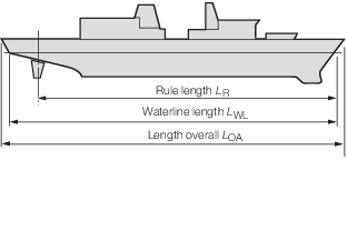
Figure 1.5.1 Lengths
5.2.8
Waterline
breadth, B
WL, is generally the greatest
moulded breadth, in metres, measured at the design draught, as shown
in Figure 1.5.2 Tranverse dimensions.
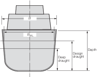
Figure 1.5.2 Tranverse dimensions
5.2.9
Breadth, B, is generally the greatest moulded breadth,
in metres, throughout the depth of the ship or as defined in appropriate
Chapters. For vessels of unusual cross-section the breadth will be
specially considered.
5.2.10
Depth,
D, is measured, in metres, at amidships, from
top of keel plate to the moulded deck line at side on the uppermost
continuous deck, or as defined in appropriate Chapters or standards.
When a rounded gunwale is arranged, the depth D is to
be measured to the continuation of the moulded deck line at side.
5.2.11
Draught, T, is the design draught, in metres, measured
from moulded baseline.
5.2.12
Block
coefficient, C
b , is the block coefficient
at draught T corresponding to a waterline at the design
draught, based on Rule length L
R and breadth B
WL, as follows:
|
C
b
|
= |

|
5.2.13 Design draught (scantling draught) is measured from the waterline when the
vessel is in the deep draught condition plus any specified design, build or Owners
margins, see
Vol 1, Pt 3, Ch 1, 5.3 Margins. Where specified, a higher waterline may be used for any temporary
operational conditions exceeding the design draught, for example a docked down
condition.
5.2.14 Deep draught is measured at a displacement such that the ship is in all
respects complete, and is fully loaded with full complement, stores, fuel, water and
payload plus any specified growth margin, see
Vol 1, Pt 3, Ch 1, 5.3 Margins. A deep operational draught may be defined for machinery trials and
performance measurement where the deep draught is unachievable at the start of life.
Where a vessel has an assigned load line, the deep draught is not to be less than the
summer load line draught.
5.2.15 Payload
is the equipment and stores that are carried by the vessel for the
purposes of fulfilling its operational requirements.
5.3 Margins
5.3.1 Design
margin is an allowance for uncertainties used in the estimation of
weight for design purposes.
5.3.2 Build
margin is an allowance for unforeseen changes that may need to be
made by the builder of the vessel.
5.3.3 Owners margin is an allowance to cater for modifications made by the Owner
to the vessel or equipment during the design and build stages.
5.3.4 Growth margin is an allowance for future controlled and uncontrolled weight
growth over the design life of the ship.
5.3.5 In the
absence of any specific requirements, the sum of the margins is be
taken as 15 per cent of the displacement at the deep draught.
5.4 Decks
5.4.1 Strength
deck is normally the uppermost continuous deck. Other decks may be
considered as the strength deck provided that such decks are structurally
effective. Where the upper deck is stepped, as in the case of vessels
with a quarter deck, the strength deck is stepped, see
Vol 1, Pt 6, Ch 4, 1 General.
5.4.2 The
weather deck is generally the lowest continuous deck exposed to sea
and weather loads. It is to be defined at the early stages of design
in conjunction with LR and the Builder.
5.4.3 Other
decks that are exposed to sea loads are to be assessed in accordance
with the requirements for weather decks.
5.4.4 The damage control deck is the lowest deck on which continuous fore and aft
access is provided to aid communications and recovery following damage. It is normally
located above the lowest vertical limit of watertight integrity at the centreline, the
exact location being determined by the relevant sub-division and watertight integrity
standard.
5.5 Co-ordinate system
5.5.1 Unless
otherwise stated, the co-ordinate system is as shown in Figure 1.5.3 NSR Co-ordinate system, that is, a right-hand
co-ordinate system with the X axis positive forward, the Y axis positive
to port and the Z axis positive upwards. Angular motions are considered
positive in a clockwise direction about the X, Y or Z axes.
5.6 Superstructure
5.6.1 For
the purposes of strength assessment a superstructure is defined as
a decked structure on the strength deck, extending from side to side
of the vessel, or with its side plating being less than four per cent
of the breadth, B, inboard of the shell plating.
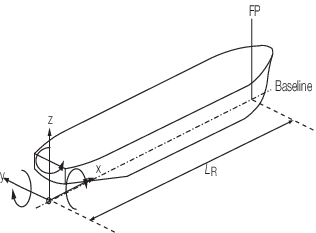
Figure 1.5.3 NSR Co-ordinate system
5.7 Deckhouse
5.7.1 A deckhouse
is in general defined as a decked structure on or above the strength
deck with its side plating being four per cent or more of the breadth, B, inboard of the shell plating.
5.8 Weathertight
5.8.1 A boundary
or closing appliance is considered weathertight if it is capable of
preventing the passage of water into the ship in any sea conditions.
5.9 Watertight
5.9.1 A boundary
or closing appliance is considered watertight if it is capable of
preventing the passage of water in either direction under a head of
water for which the surrounding structure is designed.
5.10 Terminology
5.11 Extent of watertight subdivision
5.11.1 The
minimum extent of watertight subdivision (internal), and integrity
(internal and external), is to be in accordance with the specified
subdivision and stability standard(s).
5.11.2 The
minimum extent of watertight subdivision may be defined by a combination
of decks, side shell and bulkheads or by a single deck.
5.11.3 Weathertight
and watertight fittings and closing appliances are to be fitted in
accordance with the requirements of the boundary on which they are
placed.
5.12 Critical compartments
5.12.1 A
critical compartment is one which, at battle stations, contains equipment
or personnel without whom functions critical to combat survivability
would be lost. These functions include the ability to fight, manoeuvre
or communicate.
5.12.2 Critical
compartments are typically the chart room, operations room, conning
position, ship’s control room and main communications office.
Other compartments may be considered critical depending on ship’s
layout and design. The need for protecting critical compartments can
be reduced by avoiding single point failure nodes and by concentrating
and protecting those which cannot be avoided. A vulnerability analysis
can be used to identify vulnerable critical compartments and the essential
pieces of equipment or systems that are required to be protected, see
Vol 1, Pt 3, Ch 1, 2.2 Submission of direct calculations.
5.12.3 Critical
pipe and cable runs are routes in which the connections for survivability
critical components run. They can cover individual routes or concentrated
areas. An example is a run containing wave guides and signal cables
for all the above water sensors on the mast.
5.13 Units system
5.13.1 Unless
otherwise stated, the variables used in the Rules are expressed in
the following units.
5.13.2
General
Distances
Primary spacings
Secondary
spacings
|
m
m
mm
|
5.13.3
Hull
girder properties
Dimensions
Area
Section modulus
Inertia
Area-moment
|
m
m2
m3
m4
m3
|
5.13.4
Stiffeners
Area
Dimensions
Inertia
Section
modulus
Length/length effective
|
cm2
mm
cm4
cm3
m
|
5.13.5
Plating
Breadth
Length
Thickness
|
mm
m
mm
|
5.13.6
Loads
Pressures
Loads
Bending moment
Shear force
|
kN/m2
kN
kN-m
kN
|
5.13.7
Other
items
Yield strength
Stress
Deflections
Modulus of
Elasticity
|
N/mm2
N/mm2
mm
N/mm2
|
|