8.5.1 Rubbing
strakes or barwhales are to be fitted to the bottom shell. In longitudinally
framed ships they are to be placed directly below longitudinals. Typical
arrangements of rubbing strakes are shown in Figure 2.8.2 Rubbing strakes. Usually they consist
of a steel frame welded to the hull supports with a bolted connection
to softer material but rubbing strips can be constructed of solid
steel sections. They are to be free of projections or other discontinuities
which could lead to damage of the shell plating.
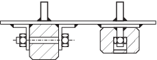
Figure 2.8.2 Rubbing strakes
8.5.2 It is
recommended that rubbing strakes are not to be spread more than 1,5m
apart. For rubbing strakes spaced greater than 1,5m the bottom structure
is to be specially considered.
8.5.3 The
rubbing strake housing both internally and externally is to be efficiently
coated to prevent corrosion. Where different materials are used the
materials are to be selected or insulated to ensure that there is
no galvanic corrosion.
8.5.4 Rubbing
strakes are to be continuously welded to the hull. Butts between sections
of rubbing strake are to be butt welded together before being welded
to the hull. Where this is not possible, ceramic rather than copper
backing strips are to be used.
8.5.5 Rubbing
strakes are to be of the same grade of steel as the shell plate to
which they are attached.
8.5.6 The
ends of rubbing strakes are to be tapered at an angle of not less
than 1 in 3 with no discontinuities in the welding in this region.
Where not supported by internal longitudinals, the ends of strakes
are to be arranged to pass 30 to 50 mm over the end of transverse
frames or floors.
8.5.7 Due
consideration is to be given to the depth of the rubbing strakes with
regard to the nature of the beach. In no case are they to be less
than 100 mm projection.