
Section
5 Dynamic loading
5.1 General
5.1.1 The
following formulae are to be used to determine the dynamic response
of plate and plate stiffener combinations. The natural frequency of
structural items can be determined from Vol 1, Pt 6, Ch 2, 4 Vibration control and the period T may then be determined as follows:
|
T
|
= |

|
where
5.1.2 For bottom impact pressure loads and bow flare and above waterline impact
pressure loads required by Vol 1, Pt 6, Ch 3, 14 Strengthening for bottom slamming and Vol 1, Pt 6, Ch 3, 15 Strengthening for wave impact loads above waterline respectively, the impact pressure is assumed to be represented by a
triangular pulse load. The rise time, t1, for these impact pressures
is given in Vol 1, Pt 5, Ch 3, 4.2 Bottom impact pressure, IPbi 4.2.2 for bottom impact and Vol 1, Pt 5, Ch 3, 4.3 Bow flare and wave impact pressures, IPbf 4.3.2 for bow flare impact.
5.1.3 For flight deck landing loads, the emergency landing load can be represented by a
triangular pulse load. The rise time, t1, for these impact pressures
can be estimated from the time taken to depress the tyre and oleo strut to their maximum
deflection and the assumed maximum vertical landing velocity. For fixed wing aircraft,
the rise time for a structural element will also depend on forward speed as the aircraft
traverses the structure.
5.2 Gradually applied load
5.3 Instantaneous load
5.4 Triangular pulse load
5.4.1 For
a triangular pulse load as shown in Figure 2.5.3 Triangular pulse load, the maximum dynamic load factor DLF be calculated from Table 2.5.1 Tabulated dynamic load
factors. Linear interpolation
may be performed to obtain DLF Rules for intermediate t
1/T values. The t
1 time
value is given in the same section that the impulsive pressure load
is specified.
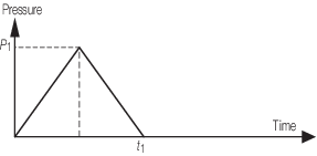
Figure 2.5.3 Triangular pulse load
5.4.2 The
time to maximum response can be calculated from Table 2.5.1 Tabulated dynamic load
factors with intermediate values
determined by linear interpolation.
Table 2.5.1 Tabulated dynamic load
factors
|
|
Dynamic load factor
|
Time to maximum displacement
|
|
t
1/T
|
Gradual
|
Triangular
|
Instant
|
Gradual
|
Triangular
|
Instant
|
|
|
f
DLF
|
f
DLF
|
f
DLF
|
t
m/t
1
|
t
m/2t
1
|
t
m/T
|
| 0,0
|
2,0
|
0,0
|
0,0
|
|
|
|
| 0,1
|
1,984
|
0,312
|
0,300
|
5,800
|
2,484
|
0,284
|
| 0,2
|
1,935
|
0,608
|
0,600
|
3,000
|
1,700
|
0,316
|
| 0,3
|
1,858
|
0,875
|
0,850
|
2,100
|
1,361
|
0,348
|
| 0,4
|
1,757
|
1,098
|
1,050
|
1,700
|
1,163
|
0,381
|
| 0,5
|
1,637
|
1,273
|
1,200
|
1,450
|
1,029
|
0,400
|
| 0,6
|
1,504
|
1,391
|
1,300
|
1,280
|
0,931
|
0,415
|
| 0,7
|
1,363
|
1,465
|
1,400
|
1,150
|
0,856
|
0,430
|
| 0,8
|
1,232
|
1,501
|
1,480
|
1,080
|
0,795
|
0,440
|
| 0,9
|
1,109
|
1,514
|
1,530
|
1,010
|
0,746
|
0,445
|
| 1,0
|
1,000
|
1,508
|
1,600
|
1,000
|
0,704
|
0,450
|
|
|
|
|
|
1,500(1)
|
|
|
| 1,1
|
1,089
|
1,481
|
1,630
|
1,430
|
0,668
|
0,453
|
| 1,2
|
1,156
|
1,441
|
1,660
|
1,360
|
0,637
|
0,456
|
| 1,3
|
1,198
|
1,397
|
1,690
|
1,290
|
0,609
|
0,459
|
| 1,4
|
1,216
|
1,342
|
1,715
|
1,220
|
0,585
|
0,462
|
| 1,5
|
1,212
|
1,282
|
1,725
|
1,150
|
0,563
|
0,465
|
| 1,6
|
1,189
|
1,228
|
1,730
|
1,119
|
0,544
|
0,466
|
| 1,7
|
1,151
|
1,165
|
1,730
|
1,089
|
0,526
|
0,468
|
| 1,8
|
1,104
|
1,104
|
1,745
|
1,059
|
0,510
|
0,469
|
| 1,9
|
1,052
|
1,052
|
1,748
|
1,029
|
0,495
|
0,471
|
| 2,0
|
1,000
|
1,000
|
1,750
|
1,200
|
0,481
|
0,473
|
| 2,1
|
1,047
|
0,960
|
1,756
|
1,170
|
0,520
|
0,474
|
| 2,2
|
1,085
|
0,953
|
1,763
|
1,140
|
0,540
|
0,475
|
| 2,3
|
1,111
|
0,980
|
1,769
|
1,110
|
0,560
|
0,477
|
| 2,4
|
1,125
|
1,016
|
1,775
|
1,080
|
0,580
|
0,478
|
| 2,5
|
1,127
|
1,055
|
1,781
|
1,050
|
0,600
|
0,480
|
| 2,6
|
1,116
|
1,089
|
1,786
|
1,039
|
0,590
|
0,480
|
| 2,7
|
1,095
|
1,115
|
1,79
|
1,029
|
0,580
|
0,480
|
| 2,8
|
1,067
|
1,126
|
1,797
|
1,019
|
0,570
|
0,481
|
| 2,9
|
1,034
|
1,135
|
1,802
|
1,009
|
0,560
|
0,481
|
| 3,0
|
1,000
|
1,158
|
1,800
|
1,100
|
0,550
|
0,482
|
| 3,1
|
1,032
|
1,168
|
1,800
|
1,089
|
0,545
|
0,482
|
| 3,2
|
1,059
|
1,167
|
1,808
|
|
0,540
|
0,483
|
| 3,3
|
1,078
|
1,155
|
1,812
|
|
0,535
|
0,483
|
| 3,4
|
1,089
|
1,132
|
1,817
|
|
0,530
|
0,484
|
| 3,5
|
1,091
|
1,103
|
1,821
|
|
0,525
|
0,484
|
| 3,6
|
1,084
|
1,084
|
1,825
|
|
0,520
|
0,485
|
| 3,7
|
1,070
|
1,070
|
1,829
|
|
0,515
|
0,485
|
| 3,8
|
1,059
|
1,060
|
1,833
|
|
0,510
|
0,486
|
| 3,9
|
1,025
|
1,025
|
1,837
|
|
0,505
|
0,486
|
| 4,0
|
1,000
|
1,000
|
1,825
|
|
0,500
|
0,487
|
| 4,1
|
1,024
|
0,978
|
1,828
|
|
0,505
|
0,487
|
| 4,2
|
1,045
|
0,976
|
1,831
|
|
0,510
|
0,487
|
| 4,3
|
1,060
|
0,989
|
1,835
|
|
0,515
|
0,487
|
| 4,4
|
1,069
|
1,007
|
1,838
|
|
0,520
|
0,488
|
| 4,5
|
1,071
|
1,029
|
1,842
|
|
0,525
|
0,488
|
| 4,6
|
1,066
|
1,050
|
1,845
|
|
0,530
|
0,488
|
| 4,7
|
1,055
|
1,069
|
1,849
|
|
0,535
|
0,489
|
| 4,8
|
1,039
|
1,083
|
1,852
|
|
0,540
|
0,489
|
| 4,9
|
1,020
|
1,091
|
1,855
|
|
0,545
|
0,489
|
| 5,0
|
1,000
|
1,092
|
1,850
|
|
0,550
|
0,490
|
| 5,1
|
1,019
|
1,083
|
1,853
|
|
0,545
|
0,490
|
| 5,2
|
1,036
|
1,069
|
1,856
|
|
0,540
|
0,490
|
| 5,3
|
1,049
|
1,050
|
1,859
|
|
0,535
|
0,490
|
| 5,4
|
1,056
|
1,056
|
1,862
|
|
0,530
|
0,490
|
| 5,5
|
1,058
|
1,058
|
1,865
|
|
0,525
|
0,490
|
| 5,6
|
1,054
|
1,054
|
1,868
|
|
0,520
|
0,490
|
| 5,7
|
1,045
|
1,045
|
1,870
|
|
0,515
|
0,490
|
| 5,8
|
1,032
|
1,032
|
1,873
|
|
0,510
|
0,490
|
| 5,9
|
1,017
|
1,017
|
1,876
|
|
0,505
|
0,490
|
| ≥6,0
|
1,002
|
1,002
|
1,870
|
|
0,500
|
0,491
|
NOTE
The time to maximum displacement
curve for a gradually applied load has a step at t
1/T = 1,0.
|
|