
Section
15 Strengthening for wave impact loads above waterline
15.1 General
15.1.1 This
Section may be used to determine the required scantlings for strengthening
against bow flare slamming for NS1 and NS2 type ships and for wave
impacts on the shell envelope. Direct calculations may also be used
to determine the required scantling.
15.1.2 The
required scantlings for strengthening against wave impact loads for
NS3 type ships will be specially considered on the basis of this Section.
15.1.3 The
scantling requirements contained in this Section are based on no permanent
set of plating. If acceptable, special consideration will be given
to an alternative plating performance standard where specified. Areas
designed in accordance with an alternative performance specification
are to be clearly marked on the plans. Direct calculations may be
used to determine the required scantlings.
15.2 Strengthening against bow flare wave impacts
15.2.1 The
shell envelope above the design waterline is to be strengthened against
bow flare wave impact pressures. The strengthening is to extend vertically
to the uppermost deck level, including the forecastle deck, if fitted.
15.2.3 The
thickness of the side shell is to be not less than:
where
|
CR
|
= |
panel ratio factor |
| = |
 but is not to be taken less than 0,06 or greater than 0,1 but is not to be taken less than 0,06 or greater than 0,1
|

|
= |
overall panel length,
in metres, measured along a chord between the primary members |
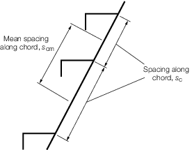
Figure 3.15.1 Chord spacing and mean chord spacing for secondary members
15.2.4 The
scantlings of primary members are not to be less than:
-
Section modulus
of primary members
-
Web area of
primary members
-
The web of the
primary member is to be adequately stiffened.
for q < 1 γA = q
3
– 2q
2 + 2 and γZ =
3q3 – 8q
2 + 6q
for q = 1 γA = 1 and γZ =
1
for web frames:
|
u
|
= |
is the minimum of g
bfv or  e
e
|
|
ν
|
= |
is the minimum
of g
bfh or S
cm
|
for primary stringers:
where
|
u
|
= |
is the minimum of g
bfh or  e
e
|
|
ν
|
= |
is the minimum
of g
bfv or S
cm
|
g
bfv and g
bfh are
defined in Vol 1, Pt 5, Ch 3, 4.3 Bow flare and wave impact pressures, IPbf 4.3.3
Other symbols are as defined in Vol 1, Pt 6, Ch 2, 1 General.
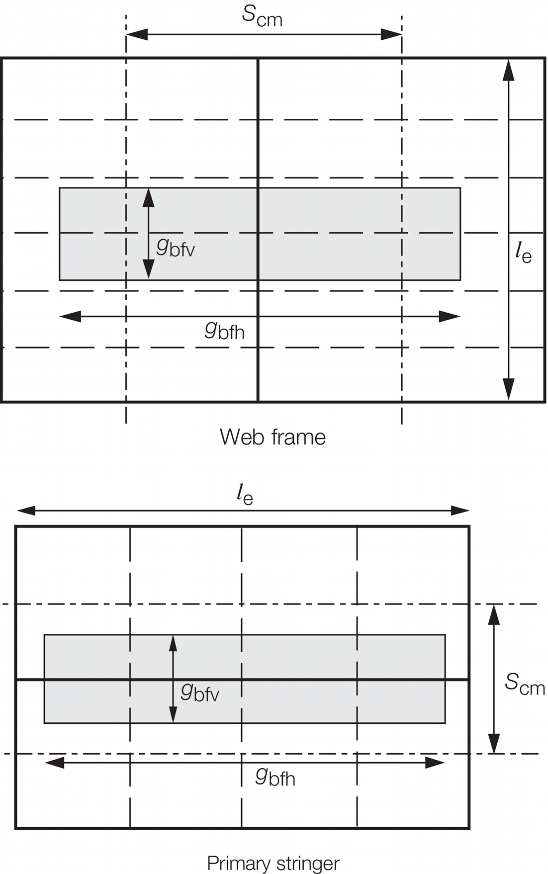
Figure 3.15.2 Mean spacing between primary
members, S
cm and the extents of the bow flare wave impact pressure, g
bfh and g
bfv
15.2.6 The
effective section properties of secondary stiffeners are to be taken
as:
-
Plastic section
modulus of secondary stiffeners, Z
p is to
be taken as:
|
Z
p
|
= |
(2,8 x 10⁻⁴ scm
t
p
2) - (10-3
b
f
b
fc
t
f sinθe) + (5 x
10-4 (h
w
2
t
w + 2b
f
t
f
h
w) cosθe) cm3
|
- where
|
θe
|
= |
Co (90 -ϕ )
|
|
Co
|
= |
1,1 |
|
ϕ |
= |
the angle
between the stiffener and the side shell, in degrees |
|
bfc
|
= |
0,5(b
f - t
w)
for L profiles
|
|
|
= |
0 for flat bar
and T profiles |
|
|
= |
 see
Figure 2.2.1 Dimensions of longitudinals in Chapter 2, for bulb profiles for
c
see
Figure 2.2.1 Dimensions of longitudinals in Chapter 2, for bulb profiles for
c
|
|
hw
|
= |
height of web, in mm |
|
tw
|
= |
web thickness, in mm |
|
bf
|
= |
breadth of flange, in mm |
|
tf
|
= |
flange thickness, in mm |
|
tp
|
= |
thickness of attached plating, in mm |
|
scm
|
= |
defined
in Vol 1, Pt 6, Ch 3, 15.2 Strengthening against bow flare wave impacts 15.2.5.
|
-
Web area of secondary
stiffeners, A
s is to be taken as:
|
A
s
|
= |
0,01 (h
w + t
p) t
w sinϕ cm2
|
15.2.7 For
primary members with cut-outs for the passage of secondary stiffeners,
and which may have web stiffeners connected to the secondary stiffener,
buckling checks are to be carried out to ensure that the primary member
web plating and web stiffener will not buckle under the design load.
The buckling procedure to be followed is given in Table 3.15.1 Buckling procedure for primary
member web plating and web stiffener Where the web stiffener
is fitted with a bracket, the buckling capability of the web stiffener
in way of the cut-out is to take into account the bracket. Where no
web stiffener is fitted, the buckling capability of the primary member
web plating is to be checked for the total load transmitted to the
connection.
15.2.8 The
structural scantlings required in areas strengthened against bow flare
wave impact are to be tapered to meet the normal shell envelope requirements.
15.2.9 Where
the stiffener web is not perpendicular to the plating, tripping brackets
may need to be fitted in order to obtain adequate lateral stability.
15.2.10 Where
the angle between the primary structure web and the plating is less
than 70°, the effective section modulus and shear area are to
take account of the non-perpendicularity.
15.3 Strengthening against wave impact loads
15.3.1 The
requirements of Vol 1, Pt 6, Ch 3, 15.2 Strengthening against bow flare wave impacts are to
be applied to areas of plating which are liable to be subjected to
wave impact loads; for example, bottom plating of wide transom sterns,
undersides of sponsons for aircraft lifts.
Table 3.15.1 Buckling procedure for primary
member web plating and web stiffener
| Steps
|
Members
|
| Primary member
web plating
|
Primary member
web stiffener
|
| Determination of the
design compressive stress, σa, N/mm2
(kgf/mm2)
|
|
|
Determination of
the elastic critical buckling stress, σe, in
compression,
N/mm2 (kgf/mm2)
|
|
|
| Determination of the
corrected critical buckling stress, σcr, in compression,
N/mm2 (kgf/mm2)
|
σcr = σ0

σcr = σe
|
where
σe> 
where σe ≤ 
|
| Requirement
|
σcr ≥ σa
|
| Symbols
|
bw, bs,  w and w and  s are dimensions, in mm, as shown in Figure 3.15.3 Dimensions of critical areas of (a) primary member web plating and (b) primary member web stiffener s are dimensions, in mm, as shown in Figure 3.15.3 Dimensions of critical areas of (a) primary member web plating and (b) primary member web stiffener
|
|
|
|
|
|
ts
|
= |
thickness of primary member web stiffener, in mm |
|
|
tw
|
= |
thickness of primary member web plating, in mm |
|
|
|
|
|
|
E
|
= |
modulus of elasticity, in N/mm2
|
| = |
206000 N/mm2 for steel |
|
|
Is
|
= |

|
|
|
Iw
|
= |

|
|
|
P
|
= |
total load transmitted to the connection |
| = |
10,06 S
cm
s
cm
h
s x 10–3 kN |
|
|
Ps
|
= |
load transmitted through the primary member web
stiffener, in kN, to be determined from P
2 = P – P
1, in kN, or by direct calculations. Where P
1 = pressure transmitted through collar arrangement and
P = total load transmitted to the primary member |
|
|
Pw
|
= |
load transmitted through the primary member web
plating, in kN |
| = |
P – P
s, or by direct calculations |
|
|
|
|
σo
|
= |
specified minimum yield stress, in N/mm2
|
|
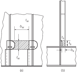
Figure 3.15.3 Dimensions of critical areas of (a) primary member web plating and (b) primary member web stiffener
|