
Section
14 Strengthening for bottom slamming
14.1 General
14.1.1 This
section may be used to determine the additional scantlings for strengthening
in respect of the bottom structure forward for NS1 and NS2 type ships.
14.1.2 The
additional scantlings for strengthening in respect of the bottom structure
forward for NS3 type ships will be specially considered on the basis
of this Section.
14.2 Strengthening of bottom forward
14.2.1 The bottom forward is to be additionally strengthened where the ship has a
draught forward of less than 0,045LR in any operational loading
condition. The minimum draught, TFB, see
Vol 1, Pt 6, Ch 3, 14.2 Strengthening of bottom forward 14.2.7 (NS1) or Vol 1, Pt 5, Ch 3, 1.3 Symbols and definitions 1.3.1 (NS2 or NS3), is to be indicated
on the shell expansion plan, the plan showing the internal strengthening, the Loading
Manual and loading instrument, where fitted.
14.2.2 The requirements for the additional strengthening apply to ships where
LR is greater than 65 m.
14.2.3 The
scantling requirements outside the areas which have been strengthened
for bottom slamming are to be suitably tapered to maintain adequate
continuity of strength in both longitudinal and transverse directions.
Table 3.14.1 Additional strengthening of bottom
forward
| Item
|
Requirements
|
(1)
Longitudinally framed bottom shell plating (including keel)
(see Notes 1 and 2)
|
t = 0,003s f

|
| (2) Bottom
longitudinals – other than flat bars
|


|
| (3) Bottom
longitudinals – flat bars
|
Will be specially considered
|
|
|
Transverse framing
|
Longitudinal framing
|
| (4) Primary structure in
way of single bottoms
|
(a)
|
Centreline
girder:
Scantlings as required by Table 3.3.12 Single bottom construction
forward, minimum requirements as appropriate, except that in
determining Z in way of a deep tank forward of
0,8LR the value of h5 is to be
increased by the following percentages:
where
TFB ≤ 0,03L
2, 30 per cent
where TFB ≥
0,04L2, 0 per cent
The increase in
h5 for intermediate values of TFB
to be obtained by interpolation
|
(a)
|
Ships having one or more longitudinal
bulkheads:
(i) Centreline girder
Scantlings
as required by Table 3.3.12 Single bottom construction
forward, minimum requirements as appropriate
(ii)
Bottom transverses
Maximum spacing as for midships region,
scantlings as required by Section 2, as appropriate
(iii) For
horizontally stiffened longitudinal bulkheads and girders the depth to
thickness ratio of the panel attached to the bottom shell plate is not to
exceed 55 
(iv) Where TFB
<0,025L2 the scantlings and arrangements will
receive individual consideration
|
| (b)
|
Floors:
Scantlings as required by Table 3.3.12 as appropriate, except that in
way of dry spaces the minimum face area is to be increased by the
following percentages:
where T
FB ≤ 0,03L2, 50 per
cent
where TFB ≥
0,04L2, 0 per cent
The increase of
minimum face area for intermediate values of TFB to be
obtained by interpolation
|
(b)
|
Other ship arrangements will
receive individual consideration
|
| (c)
|
Side
girders:
Arrangement and scantlings as required by Table 3.3.12 Single bottom construction
forward, minimum requirements as appropriate, with the
addition of intermediate half-height girders or equivalent fore and aft
stiffening
|
|
|
| (5) Primary structure in
way of double bottoms (see Note 3)
|
(a)
|
Plate
floors:
Maximum spacing, every
frame
Scantlings as required by Vol 1, Pt 6, Ch 3, 2 Minimum structural requirements
|
(a)
|
Plate floors:
Maximum spacing:
0,002sF m for
T
FB < 0,04L
2
0,003sF m for T
FB ≥ 0,04L
2
but not to exceed that required by Table 3.3.12 Single bottom construction
forward, minimum requirements as appropriate
|
| (b)
|
Centreline and side
girders:
Maximum spacing,
0,003sF m
Scantlings as required by Vol 1, Pt 6, Ch 3, 2 Minimum structural requirements
|
(b)
|
Centreline and side
girders:
Maximum
spacing:
0,003s
L m for T
FB < 0,04L
2
0,004s
L m for T
FB ≥ 0,04L
2
but not to exceed that required by Table 3.3.12 Single bottom construction
forward, minimum requirements, as appropriate
|
| (c)
|
Intermediate
half-height girders to be arranged midway between side girders:
|
Scantlings as required by Table 3.3.12 Single bottom construction
forward, minimum requirements, as appropriate
|
| Scantlings as required for non-watertight side
girders by Section 2
|
| (6) Primary
structure in way of double bottoms supported by longitudinal
bulkheads
|
—
|
The scantlings and arrangements will receive
individual consideration on the basis of direct calculations using, if
necessary, a suitably defined two-dimensional grillage model
|
| Symbols
|
| L
R, T as defined in Vol 1, Pt 3, Ch 1, 5.2 Principal particulars
|
| L
2, S, s, k
s as defined in Vol 1, Pt 6, Ch 3, 3.2 Symbols 3.2.1
|
|
|
|
|
= |
(0,87 + 0,16S) c
1 for S > 2,5 m |
|
|
|
|
|
= |
(1,14 – 0,14S) for 1,0 m < S ≤ 4,0 m |
|
|
|
= |
 for S > 4,0 m for S > 4,0 m |
|
|
|
|
f
|
= |
 but not greater than 1,0 but not greater than 1,0 |
|
|
|
|
|
|
|
= |
S, in metres, where in way of a single bottom |
|
|
p
|
= |
9,81h
s
sc
1
 x 10-3 kN x 10-3 kN |
|
|
s
F
|
= |
spacing of transverse frames, in mm, for
longitudinally framed side and bottom construction s
F may be taken as s
L
|
|
|
s
L
|
= |
spacing of bottom longitudinals, in mm |
|
|
t
w
|
= |
web thickness, in mm |
|
|
A
f
|
= |
cross-sectional area of primary member web stiffener,
in cm2
|
|
|
A
fc
|
= |
effective area of primary member web stiffener in way
of butted end connection to the longitudinal, in cm2
|
|
|
A
L
|
= |
area of weld of lapped connection, in cm2,
calculated as total length of weld, in cm x throat thickness, in cm |
|
|
A
w
|
= |
area of weld of lug and web connection to the
longitudinal, in cm2, calculated as total length of weld
in cm x throat thickness, in cm |
|
|
A
1
|
= |
effective total cross-sectional area of the lug and
web connection to the longitudinal, in cm2
|
|
|
|
|
α |
= |
A
f
 for the web stiffeners for the web stiffeners |
|
|
|
= |
A
fc
 for a butted connection to the longitudinals for a butted connection to the longitudinals |
|
|
|
= |
A
L
 for a lapped connection for a lapped connection |
|
|
|
|
|
Note
1. If intermediate stiffening is fitted
the thickness of the bottom shell plating may be 80 per cent of that
required by (1) but is to be not less than the normal taper
thickness.
|
Note
2. For transverse framing the bottom
shell plating is to be specially considered.
|
Note
3. Particular care is to be taken to
limit the size and number of openings in way of the ends of floors or
girders or to fit suitable reinforcement where such openings are
essential.
|
|
|
Table 3.14.2 Permissible stresses
14.2.5 Bottom
longitudinals are to pass through and be supported by the webs of
primary members. The vertical web stiffeners are to be connected to
the bottom longitudinals. The cross-sectional area of the connections
is to comply with the requirements given in Table 3.14.1 Additional strengthening of bottom
forward
14.2.7 For NS1 ships with a block coefficient, Cb, greater than
0,6, the equivalent slamming pressure expressed as a head of water,
hs, is to be obtained from Figure 3.14.1 Pressure heads where hmax is calculated
from the following expressions:
where
 is the minimum draught, in metres, at the location under
consideration for all operational loading conditions, and is to be measured from the
underside of the keel to the operational waterline is the minimum draught, in metres, at the location under
consideration for all operational loading conditions, and is to be measured from the
underside of the keel to the operational waterline
LR is as defined in Vol 1, Pt 3, Ch 1, 5.2 Principal particulars
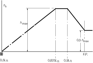
Figure 3.14.1 Pressure heads
14.2.8 For NS1 ships where Cb < 0,6 and for NS2 and NS3
ships, the equivalent bottom impact pressure head, hs, is to be
derived in accordance with the following:
where
|