
Section
9 Bulwarks, guard rails, raised walkways and other means for the
protection of crew and embarked personnel
9.1 General requirements
9.1.1 Bulwarks or guard rails are to be provided at the boundaries of exposed
decks. Bulwarks or guard rails are to be not less than 1,0 m in height measured above
sheathing, and are to be constructed as required by this Section. Consideration will be
given to cases where this height would interfere with the normal operation of the ship.
Guard rails provided around aircraft operating areas may be of the type which drop
outwards with nets which are to comply with Vol 1, Pt 3, Ch 4, 9.6 Safety nets. Droppable guard rails must be capable of being secured
in both the upright and lowered position. Where bulwarks or guard rails are undesirable,
e.g. for radar signature purposes, alternative equivalent arrangements will be required.
Guidance on radar signatures is provided in Vol 1, Pt 4, Ch 1, 4.1 Radar signature.
9.1.3 Guard
rails fitted on superstructure and exposed decks are to have at least
three courses. The opening below the lowest course of guard-rails
is not to exceed 230 mm. The other courses are to be spaced not more
than 380 mm apart. In the case of ships with rounded gunwales, the
guard-rail supports are to be placed on the flat of the deck. In other
locations, guard rails with at least two courses are to be fitted.
9.1.4 Guard rails are to be fitted with fixed, removable or hinged stanchions
fitted no more than 1,5 m apart. Removable or hinged stanchions shall be capable of
being locked in the upright position. When retracted, collapsed or removed, the guard
rails are not to impede access/egress. Stowage is to be provided for portable stanchions
and stays, sited adjacent to where they are to be used.
9.1.5 At least
every third stanchion is to be supported by a stay.
9.1.6 Where
necessary for the normal operation of the ship, steel wire ropes may
be accepted in lieu of guard rails. Wires are to be made taut by means
of turnbuckles. Chains are only permitted in short lengths in way
of access openings.
9.1.7 Satisfactory means for safe passage of personnel, in the form of guard
rails, life-lines, handrails, gangways, underdeck passageways or other equivalent
arrangements, are to be provided for the protection of the crew and embarked personnel
in getting to and from their quarters, the machinery space and all other spaces used in
the operation of the ship.
9.1.8 A well
illuminated and ventilated underdeck passage (with a clear opening
at least 0,8 m in width and 2 m in height) is to be provided as close
as practicable to the weatherdeck, connecting and providing access
to the following locations:
- between superstructures;
- from the forwardmost superstructure to the forward end of the
vessel;
- from the aftmost superstructure to the aft end of the vessel.
9.1.9 A means of passage over obstructions such as pipes or other fittings of a permanent
nature is to be provided where practicable.
9.1.10 To
assist movement in adverse weather conditions, handrails are to be
fitted to bulkheads in passageways and superstructure on weatherdecks.
9.1.11 Handrails
are to be fitted at a height of not less than 1 m, measured from the
top of the rail to the deck. Handrails should be made of steel tubes
of 42,4 mm outside diameter, with a wall thickness of at least 2,6
mm.
9.1.12 Handrails
are to be secured by way of supports that are not to be spaced more
than 1,5 m apart. The supports are to hold the rails not less than
50 mm from the bulkhead, measured from the inside of the rail to the
bulkhead.
9.1.13 Raised
walkways which form escape routes or assembly areas, or provide for
the transfer of heavy equipment, stores or munitions, are to comply
with the requirements of Vol 1, Pt 3, Ch 4, 9.5 Walkways.
9.2 Bulwark construction
9.2.1 Plate
bulwarks are to be stiffened by a strong rail section and supported
by stays from the deck. The spacing of these stays forward of 0.93L
R is to be not more than 1,2 m. Elsewhere, bulwark
stays are to be not more then 1,83 m apart. Where bulwarks are cut
to form a gangway or other opening, stays of increased strength are
to be fitted at the ends of the openings. Bulwarks are to be adequately
strengthened in way of eyeplates for RAS points, and in way of mooring
pipes the plating is to be doubled or increased in thickness and adequately
stiffened.
9.2.2 Bulwarks
should not be cut for gangway or other openings near the breaks of
superstructures, and are also to be arranged to ensure their freedom
from main structural stresses. See shell plating in appropriate
Chapters.
9.2.3 The
section modulus, Z, at the bottom of the bulwark stay
is to be not less than:
|
Z
|
= |
(33,0
+ 0,44L) h
2
s cm3
|
where
|
h
|
= |
height
of bulwark from the top of the deck plating to the top of the rail,
in metres |
9.2.4 In the
calculation of the section modulus, only the material connected to
the deck is to be included. The bulb or flange of the stay may be
taken into account where connected to the deck, and where, at the
ends of the ship, the bulwark plating is connected to the sheerstrake,
a width of plating not exceeding 600 mm may also be included. The
free edge of the stay is to be stiffened.
9.2.5 Bulwark
stays are to be supported by, or to be in line with, suitable underdeck
stiffening, which is to be connected by double continuous fillet welds
in way of the bulwark stay connection.
9.3 Freeing arrangements
9.3.1 The
following requirements are applicable to all ship types.
9.3.2 Where
bulwarks on the weather decks or superstructure decks form wells,
ample provision is to be made for rapidly freeing the decks of large
quantities of water by means of freeing ports, and also for draining
them.
9.3.3 The
minimum freeing area on each side of the ship, for each well on the
weather deck is to be derived from the following formulae:
-
where the length,
l, of the bulwark in the well is 20 m or less: area required
= 0,7 + 0,035l m2
-
where the length,
l, exceeds 20 m, area required = 0,07l m2
l need not be taken greater than 0,7L
R,
where L
R is the length of the ship as defined
in Vol 1, Pt 3, Ch 1, 5.2 Principal particulars.
9.3.4 If the
average height of the bulwark exceeds 1,2 m or is less than 0,9 m,
the freeing area is to be increased or decreased, respectively, by
0,004 m2 per metre of length of well for each 0,1 m increase
or decrease in height respectively.
9.3.6 Two-thirds
of the freeing port area required is to be provided in the half of
the well nearest to the lowest point of the sheer curve.
9.3.7 When
the deck has little or no sheer, the freeing area is to be spread
along the length of the well.
9.3.8 In ships
with no sheer the freeing area as calculated from Vol 1, Pt 3, Ch 4, 9.3 Freeing arrangements 9.3.3 is to be increased by 50 per
cent. Where the sheer is less than the standard, as given in Table 4.9.1 Standard sheer profile, the percentage is to
be obtained by linear interpolation.
Table 4.9.1 Standard sheer profile
| Position from A.P.
|
Ordinate (in mm)
|
| A.P.
|
|
| 0,16L
R
|
|
| 0,33L
R
|
|
| 0,5L
R
|
0
|
| 0,67L
R
|
|
| 0,83L
R
|
|
| F.P.
|
|
Note
1. Sheer is measured from the deck at
side to a line drawn parallel to the keel through the sheer line
amidships.
Note
2. In ships with a rake of keel, the
sheer is measured in relation to a reference line drawn parallel to
the design waterline.
|
9.3.9 Where
the length of the well is less than 10 m, or where a deckhouse occupies
most of the length, the freeing port area will be specially considered
but in general need not exceed 10 per cent of the bulwark area.
9.3.10 Where
it is not practical to provide sufficient freeing port area in the
bulwark, particularly in small ships, credit can be given for bollard
and fairlead openings where these extend to the deck.
9.3.11 Where
a deckhouse has a breadth less than 80 per cent of the beam of the
ship, or the width of the side passageways exceeds 1,5 m, the arrangement
is considered as one well. Where a deckhouse has a breadth equal to
or more than 80 per cent of the beam, B, of the ship,
or the width of the side passageways does not exceed 1,5 m, or when
a screen bulkhead is fitted across the full breadth of the ship, this
arrangement is considered as two wells, before and abaft the deckhouse.
9.3.12 Suitable
provision is also to be made for the rapid freeing of water from recesses
formed by superstructures and deckhouses, etc. in which water may
be shipped and trapped. Deck gear is not to be stowed in such a manner
as to obstruct unduly the flow of water to freeing port.
9.3.13 The
lower edges of freeing ports are to be as near to the deck as practicable,
and should not be more than 100 mm above the deck.
9.3.14 Where
freeing ports are more than 230 mm high, vertical bars spaced 230
mm apart may be accepted as an alternative to a horizontal rail to
limit the height of the freeing port.
9.3.15 Where
shutters are fitted, the pins or bearings are to be of a non-corrodible
material, with ample clearance to prevent jamming. The hinges are
to be within the upper third of the port. Shutters are not to be fitted
with securing appliances.
9.3.16 All
ships are to have open rails for at least half the length of the exposed
part of the weather deck. Alternatively, if a continuous bulwark is
fitted, the minimum freeing area is to be at least 33 per cent of
the total area of the bulwark. The freeing area is to be placed in
the lower part of the bulwark.
9.3.17 In
ships having superstructures which are open at either or both ends
to wells formed by bulwarks on the open deck, adequate provision for
freeing the open spaces are to be provided as follows:
The freeing port area, A
w for the open
well:
The freeing port area, A
s for
the open superstructure:
where
|
lw
|
= |
the
length of the open deck enclosed by bulwarks, in metres. |
|
ls
|
= |
the
length of the common space within the open superstructure, in metres |
|
b
o
|
= |
breadth of openings in the end bulkhead of the enclosed superstructure,
in metres |
|
h
w
|
= |
distance of the well deck above the freeboard deck, in metres |
|
h
s
|
= |
one standard superstructure height |
|
h
b
|
= |
actual height of the bulwark, in metres |
|
A
c
|
= |
bulwark height correction factor taken as; |
| = |
0 for bulwarks between 0,9 and 1,2 m in height |
| = |
 for bulwarks of height greater than 1,2 m and for bulwarks of height greater than 1,2 m and
|
| = |
 for bulwarks of height greater than 0,9 m for bulwarks of height greater than 0,9 m
|
To adjust the freeing port area for the distance
of the well deck above the weatherdeck, for decks located more than
0,5h
s above the weatherdeck, multiply by the
factor 0,5 (h
s/h
w).
9.3.18 Where
a ship operates for extended periods in a cold weather environment, see
Vol 1, Pt 5, Ch 2, 4.2 Definitions 4.2.3,
closing devices fitted to freeing port arrangements are to remain
effective. The arrangement will be specially considered.
9.4 Free flow area
9.4.1 The
effectiveness of the freeing port area in bulwarks of vessels not
fitted with a continuous deck obstruction, depends on the free flow
across the deck.
9.4.2 The
free flow area is the net total longitudinal area of the transverse
passageways or gaps between hatchways and superstructures or deckhouses,
due account being made for any obstructions such as equipment or other
fittings. The height of passageways or gaps used in the calculation
of the area is the height of the bulwark.
9.5 Walkways
9.5.1 Walkways
are to be designed to an agreed specified standard.
9.5.2 Plans
are to be submitted showing the proposed scantlings and arrangements
of the structure.
9.5.4 For
the design of the supporting structure of walkways, the applicable
self weight of the walkway structure is to be added to the total load
derived in Vol 1, Pt 3, Ch 4, 9.5 Walkways 9.5.3.
9.6 Safety nets
9.6.1 Safety netting used around flight decks is to be arranged so as to safely arrest the
fall of personnel. For this purpose the netting is to be raised at the outboard edge
by an approximate angle of 10 degrees to the horizontal. The netting is to extend a
minimum of 1,25 metres in the horizontal plane. It is recommended that the outboard
edge is not above the level of the landing area but in no case is it to protrude
greater than 250mm. Materials for the netting are to be specially considered, due
consideration is to be given to the fire resistance and weathering properties.
9.6.2 The design load applied to safety nets and their supporting structure is
to be taken as 2,7kN per metre of netting acting at the centre of the net in
addition to the self-weight of the structure. The sag of the net is to be considered
when resolving this force at the inner and outer fixings of the net, see
Figure 4.9.1 Safety netting sag. Where the netting terminates at a support, the full
load is to be applied to the support. The stress criteria to be applied for supports
and supporting structure are given in Table 4.9.2 Permissible stress.
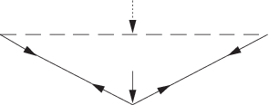
Figure 4.9.1 Safety netting sag
Table 4.9.2 Permissible stress
|
|
Permissible stress
|
| Bending and direct stress
|
0,8σo
|
| Shear stress
|
0,5σo
|
| Combined stress
|
0,9σo
|
| Symbols
|
| σo = specified
yield stress of the material, in N/mm2
|
9.7 Ladders
9.7.1 Fixed ladders of any type are to be designed in accordance with an appropriate
recognised Standard, e.g. BSMA 39-1 Vertical steel ladders, BSMA 39-2
Sloping steel ladders.
9.7.2 Ladders may be constructed from alternative materials than those specified in the
standards for the purposes of satisfying radar signature requirements. Equivalent
levels of usability and robustness are to be demonstrated.
9.7.3 When the climbing height of a single ladder is 3m or more, fall arrest features are
to be provided. Where practicable, staging platforms are to be provided for climbing
heights in excess of 6m so as to divide the climbing height into multiple
stages.
9.8 Means of embarkation and disembarkation
9.8.2 Accommodation ladders, embarkation ladders and gangways are to be in
accordance with an appropriate recognised Standard, e.g. ISO 5488 Accommodation
ladders, ISO 5489 Embarkation ladders or ISO 7061 Shipbuilding –
aluminium shore gangways for seagoing vessels.
|