4.1.1 The
Owner is responsible for determining the level of signature control
required and agreeing any resultant design to achieve the required
levels. There are however, instances where signature levels are not
specified but good design practice may be applied. The following is
offered as guidance.
4.1.2 All
constructional details on the exposed surfaces of the hull, superstructures,
masts and equipment above the design waterline should be considered
for their radar reflection properties.
4.1.3 The
Radar Cross Section (RCS) of the ship will primarily be controlled
by shaping. This concentrates the returned energy into a small number
of narrow beams, orientated in sacrificial directions or by directing
the returned energy at an angle away from the incident energy. The
extent of the orientation of the sacrificial directions should be
agreed between the Owner and designer.
4.1.4 Appropriate
modelling tools and expert judgement should be used for RCS calculation
and assessment at various stages of the design iteration. Consideration
should also be given to the RCS measurement of equipment.
4.1.5 Flare
and tumblehome as defined in Figure 1.4.1 Radar reflection are to be used where possible on all otherwise vertical
surfaces. The angle used should be greater than 6°. Consideration
should be given to using a single or multiple elevation angles, see
Vol 1, Pt 4, Ch 1, 4.1 Radar signature 4.1.3. This practice
also eliminates the dihedral reflector potentially formed between
a horizontal and a vertical surface.
4.1.6 Orthogonal
corners give rise to high radar returns in the direction of the originating
antenna. Creating dihedral or trihedral right angled reflectors should
be avoided. This applies equally to disconnected orthogonal corners,
where two (or three) surfaces do not meet but are orthogonal and a
clear line of sight exists between them. This can include items such
as: boat bays, reception areas, superstructure overhangs, sponsons
and equipment mounts.
4.1.7 Corners
which would otherwise be orthogonal should be made non-orthogonal
by a minimum of 4°, i.e. avoiding an internal angle of between
86° and 94°. Any shaping which uses angles less than 4°
could inadvertently be made ineffective by local plate deformation
or build tolerances.
4.1.8 Where
doors providing access to the deck penetrate sloped structure, it
will be desirable for the door itself to be hung vertically on its
hinges. To achieve this it is necessary to recess the door into the
sloped plate. Where this approach is adopted, the structure of the
door recess should be made non-orthogonal by rotating the vertical
sides of the recess by a minimum of 4°.
4.1.9 Avoid
single curved surfaces (such as cylinders or cones) with diameters
greater than 30 mm. Consideration should be given to replace these
items by combinations of flat plates (with appropriate orientations),
shielding or choice of appropriate material property.
4.1.10 The
use of lattice type masts and equipment supports should be avoided.
4.1.11 Consideration
should be given to reducing the amount of clutter (microgeometry)
by design, hiding it behind bulkheads or shielding (i.e. shutters
for when equipment is not in use).
4.1.12 Where
the use of homogenous reflective material is impractical for shielding,
a mesh of electrical conductive fibres with an appropriate mesh spacing
to simulate a reflective surface over the radar frequency range of
interest can be used. This can also be applied to windows and non-structural
bulkheads. Where a mesh is applied to windows which may be used for
navigation purposes consideration should be given to the effects on
visibility.
4.1.13 The
number of external ladders should be kept to a minimum. Where they
are unavoidable, ladder uprights should be rotated to avoid forming
dihedral corners with the bulkheads on which they are mounted. As
an alternative, external ladders could be constructed from a material
translucent to radar.
4.1.14 Consideration
should be given to the use of radar absorbent materials either as
appliqués or more preferably as an inherent part of the structure
i.e. Structural Radar Absorbent Material (SRAM).
4.1.15 Composites
are generally semi-transparent to radar and therefore attention should
be paid to equipment/ structures placed behind composite structures.
Alternatively, consideration can be given to altering the composite
properties, applying a metallic backing to the composite or by using
SRAM.
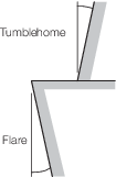
Figure 1.4.1 Radar reflection