
Section
2 Vehicle decks and fixed ramps
2.1 General
2.1.1 These
requirements are applicable to longitudinally or transversely framed
ships intended for the carriage of tracked vehicles, wheeled vehicles,
or where wheeled vehicles are to be used for cargo handling.
2.1.2 The
deck and supporting structure are to be designed on the basis of the
maximum loading to which they may be subjected in service. Where applicable,
the hatch covers are to be similarly designed. In no case, however,
are the scantlings to be less than would be required for a weather
or cargo deck, or hatch cover, as applicable.
2.1.3 Details
of the deck loading resulting from the proposed stowage or operation
of vehicles are to be supplied by the Builder. These details are to
include axle and wheel spacing, the wheel load, type of tyre and tyre
print dimensions for the vehicles. The vehicle types and wheel loads
for which the vehicle decks, including hatch covers where applicable,
have been approved are to be included in the ship’s documentation
and contained in a notice displayed on each deck. For wheeled vehicles,
the wheel loading is to be taken as not less than 3,0 kN.
2.1.4 The
scantling requirements are based on structural strength and limitations
on stress and deflection, guidance for wear and tear allowances is
given in Vol 1, Pt 4, Ch 3, 2.3 Deck plating. Local reinforcement
is to be fitted as necessary, particularly in way of vehicle lanes
and embarked personnel routes.
2.1.5 The
webs of vehicle deck stiffening members are in no cases to be scalloped.
2.1.6 If wheeled
vehicles are to be used on insulated decks or tanks tops, consideration
will be given to the permissible loading in association with the insulation
arrangements and the plating thickness.
2.1.7 Suitable
fire fighting equipment and services should be provided in the vehicle
space. Arrangements should be made for ventilation and drainage of
spilt fuel.
2.2 Definitions
2.2.1
Load
Area. The load area is defined as the footprint area of an
individual wheel or the area enclosing a group of wheels when the
distance between footprints is less than the smaller dimension of
the individual prints.
2.3 Deck plating
2.3.1 The thickness, t
p, of vehicle deck plating is to be taken as not less than:
where
|
|
= |

|
|
s
|
= |
secondary
stiffener spacing, in mm |
s and k
s are
as defined in Vol 1, Pt 4, Ch 3, 1.2 Symbols and definitions.
Table 3.2.1 Deck plate thickness
calculation
| Symbols
|
Expression
|
a, s, u and v as defined in Figure 3.2.1 Tyre print chart
|
F
typ
|
= |
corrected patch load for plating, in kN |
|
λ |
= |
dynamic magnification factor |
|
φ1
|
= |
patch aspect ratio correction factor |
|
φ2
|
= |
panel aspect ratio correction factor |
|
φ3
|
= |
wide patch load factor |
|
|
|
φ1
|
= |

|
|
|
|
|
for u ≤
(a – s)
|
|
|
= |

|
|
for a ≥
u > (a – s)
|
|
|
= |
0,77
|
|
for u > a
|
|
|
for v <
s
|
|
|
for 1,5 >
(v/s) > 1,0
|
|
|
for (v/s) ≥ 1,5
|
|
λ |
= |
1,25 for harbour conditions |
| = |
(1 + 0,7n) for sea going conditions |
|
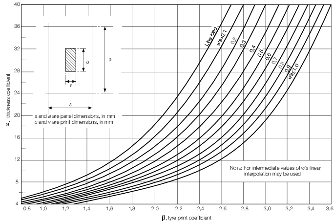
Figure 3.2.1 Tyre print chart
Table 3.2.2 Tyre correction factor, n
| Number of wheels in idealised
patch
|
Pneumatic
tyres
correction factor, n
|
Solid
rubber
tyres
correction factor, n
|
|
|
|
|
2.3.3 Where
transversely framed decks contribute to the hull girder strength or
where secondary stiffening is fitted perpendicular to the direction
of vehicle lanes, the thickness, t
p, derived
from Vol 1, Pt 4, Ch 3, 2.3 Deck plating 2.3.1 is to be increased
by 1,0 mm.
2.3.4 In the
absence of a specific requirement the thickness t
p derived
from Vol 1, Pt 4, Ch 3, 2.3 Deck plating 2.3.1 is to be increased
by a wear and wastage allowance of 1,5 mm for strength decks, weather
decks, tank tops and inner bottom or 0,75 mm elsewhere.
2.4 Secondary stiffening
2.4.1 The
scantlings of vehicle deck stiffeners are to satisfy the most severe
arrangement of print wheel loads.
2.4.2 The
minimum requirements for section modulus, inertia and web area of
vehicle deck secondary stiffeners subject to wheel loading are to
be calculated in accordance with Table 3.2.3 Secondary stiffener
requirements using the loads defined in Table 3.2.4 Design load cases for primary and
secondary stiffening and supporting structure.
Table 3.2.3 Secondary stiffener
requirements
|
Scantling requirement
|
Load
case
|
d ≤ 
|
d > 
|
| Section modulus (Z)(cm3)
|
|
|
Inertia ( )(cm4) )(cm4)
|
|
|
| Web area (A
w)(cm2)
|
where m = d/l
|
|
| Symbol
|

|
= |
overall secondary stiffener length, in metres |
|
|
s
|
= |
stiffener spacing, in metres |
|
|
d
|
= |
dimension of load area parallel to stiffener axis, in
metres |
|
|
E
|
= |
Young's Modulus of elasticity of material, in
N/mm2
|
|
|
w
|
= |
dimension of load area perpendicular to stiffener
axis, in metres |
|
|
k
w
|
= |
lateral loading factor |
| = |
1 for w ≤ s
|
| = |
s/w for w > s
|
|
|
F
tys
|
= |
point load given in Table 3.2.4, in kN |
|
|
F
tym
|
= |
self weight load given in Table 3.2.4, in kN |
|
|
P
tyw
|
= |
weather deck load given in Table 3.2.4, in
kN/m2
|
|
| f
σ,f
δ,f
τ are the structural design factors given in Pt 6, Ch 5
|
|
σo
|
= |
specified minimum yield strength of the material, in
N/mm2
|
|
|
τo
|
= |
shear strength of the material, in N/mm2
|
| = |

|
|
Table 3.2.4 Design load cases for primary and
secondary stiffening and supporting structure
| Condition
|
Loading
|
| Stiffening
|
|
|
UDL
Ptyw
kN/m2
|
Point loads,
Ftys
kN
|
Self weight,
Ftym
kN
|
| Manoeuvring
internal
|
-
|
1,6Wty
|
(1 + a
z)Ws
|
| Manoeuvring external
|
0,5
|
1,75Wty
|
(1 + a
z)Ws
|
| Parking
internal
|
-
|
(1+ n a
z)Wty
|
(1 + a
z)Ws
|
| Parking external
|
2
|
1,1
(1+ n a
z)Wty
|
(1 + a
z)Ws
|
| Symbols
|
|
W
ty
|
= |
maximum effective load per wheel or group of
wheels |
|
|
W
s
|
= |
structural weight of stiffener and supported
structure, in kN |
|
|
UDL |
= |
uniformly distributed load over entire vehicle area,
kN/m2
|
|
|
|
|
a
z is defined in Vol 1, Pt 5, Ch 3, 2 Motion response
|
Note
1. For the design of the supporting
structure for vehicle decks, the applicable self weight and horizontal
loads are to be added to the parking area loads.
|
Note
2. The vehicles are to be positioned so
as to produce the most severe loading condition for each structural
member under consideration.
|
Note
3. Stiffening members may have more than
one point load acting at any time.
|
2.4.3 When
two or more load areas are located simultaneously on the same stiffener
span, the scantling requirements are to be specially considered on
the basis of direct calculation.
2.5 Primary stiffening
2.6 Securing arrangements
2.6.2 Deck
fittings in way of vehicle lanes are to be recessed.
2.6.3 The
vehicle deck structure is to be of adequate strength for the upward
forces imposed at fixed securing points. Local reinforcement is to
be fitted as necessary.
2.7 Access
2.7.3 Doors
providing access between vehicle decks and accommodation spaces are
to be gastight, have scantlings equivalent to the surrounding structure
and where applicable are to comply with the specified fire safety
standard.
2.8 Hatch covers
2.8.1 The
scantlings and arrangements of hatches and hatch covers located within
vehicle decks are to be not less than that required by the Rules for
the supporting structure in which such hatches are fitted. In general
the end fixity of primary stiffening members is to be taken as simply
supported. Local and secondary stiffening members may be either partially
or fully fixed at their end connections dependent upon the proposed
arrangement.
2.8.2 In no
case, however, are the scantlings of plating and stiffeners to be
less than would be required for a weather or cargo deck hatch cover,
as applicable.
2.8.3 Where
unusual arrangements of hatch cover stiffening are proposed, the scantlings
of plating and stiffeners may be determined by direct calculations.
The designers calculations are to be submitted.
2.9 Heavy and special loads
2.9.1 Where
heavy or special loads are proposed to be carried, the scantlings
and arrangements of the deck structure will be individually considered
on the basis of submitted calculations.
2.9.2 Due
account is to be taken of the acceleration levels due to ship motion
as applicable to particular items of heavy mass such as vehicles,
containers, pallets, etc.
2.10 Tracked and steel wheeled vehicles
2.10.1 Where
it is proposed to carry tracked vehicles the patch dimensions may
be taken as the track print dimensions and F
w is
to be taken as half the total weight of the vehicle. Deck fittings
in way of vehicle lanes are to be recessed.
2.10.2 Where
it is proposed to carry tracked vehicles, the total weight of the
vehicle is to be used when determining the section modulus of the
transverse at the top of a ramp or at other changes of gradient.
2.11 Openings in main vehicle deck
2.11.1 Items
such as portable plates in main vehicle deck for the removal of machinery
parts, etc. may be arranged flush with the deck, provided they are
secured by gaskets and closely spaced bolts at a pitch not exceeding
five diameters.
2.11.2 Scuppers
from vehicle or cargo spaces fitted with an approved fixed pressure
water spray fire-extinguishing system are to be led inboard to tanks.
Alternatively they may be led overboard providing they comply with Vol 1, Pt 3, Ch 4, 8.1 General 8.1.3.
2.11.3 Inboard draining scuppers do not require valves but are to be led to
suitable drain tanks (not engine room or hold bilges) and the capacity of the tanks is
to be sufficient to hold at least 20 minutes of drenching water. The arrangements for
emptying these tanks are to be approved and suitable high level alarms provided.
2.11.4 Air
pipes from cofferdams or void spaces may terminate in the enclosed
‘tween deck space on the main vehicle deck provided the space
is adequately ventilated and the air pipes are provided with weathertight
closing appliances.
2.12 Direct calculations
2.12.1 Clasifications
Register (hereinafter referred to as 'LR') will consider direct calculations
for the derivation of scantlings as an alternative to and equivalent
to those derived by Rule requirements. The assumptions made and the
calculation procedures used are to be submitted for appraisal in accordance
with Vol 1, Pt 3, Ch 1, 2 Direct calculations
|