
Section
8 Anchor windlass design and testing
8.1 General
8.1.1 A windlass, capstan or winch used for handling anchors, suitable for the
size of chain cable required by Vol 1, Pt 3, Ch 5, 5 Anchor cable and complying with the following criteria is to
be fitted. Where Owners require equipment significantly in excess of Rule requirements,
it is their responsibility to specify increased windlass power.
8.1.2 The design, construction and testing of windlasses are to conform with a relevant
National or International Standard or code of practice acceptable to LR. To be
considered acceptable, the standard, or code of practice, is to specify criteria for
evaluation of stresses, performance and testing.
8.1.3 Operation and maintenance procedures for the anchor windlass are to be incorporated in
the vessel operations manual.
8.2 Plans and particulars to be submitted
8.2.1 The following plans showing the design specifications, the standard of compliance,
engineering analyses and details of construction, as applicable, are to be submitted
for evaluation:
- Windlass design specifications, anchor and chain cable
particulars, performance criteria, and standard of compliance.
- Windlass foundation drawings including the supporting
structure below deck. The details shall include bolts, chocks, shear
stoppers etc. along with the foot print loads for the specified windlass
ratings.
- Chain stopper foundation drawings including the
supporting structure below deck. The details shall include bolts, chocks,
shear stoppers etc. along with the foot print loads for the specified
rating.
- Windlass arrangement plans showing all the components of
the anchoring/mooring system such as the prime mover, shafting, cable
lifter, anchors and chain cables; mooring winches, wires and fairleads, if
they form part of the windlass machinery; brakes; controls, etc.
- Dimensions, materials, welding details, as applicable,
of all torque-transmitting components (shafts, gears, clutches, couplings,
coupling bolts, etc.) and all load-bearing components (shaft bearings,
cable lifter, sheaves, drums, bed-frames, etc.) of the windlass and of the
winch, where applicable, including brakes, chain stopper (if fitted), and
foundation.
- Hydraulic system, to include:
- piping diagram along with system design
pressure;
- safety valves arrangement and settings;
- material specifications for pipes and
equipment;
- typical pipe joints, as applicable;
- technical data and details for hydraulic
motors;
- cooling systems arrangements for hydraulic
system oil.
- Electrical one-line diagram along with cable
specification and size, motor controller, protective device rating or
setting, as applicable.
- Control, monitoring and instrumentation
arrangements.
- Engineering analyses for torque-transmitting and
load-bearing components demonstrating their compliance with recognised
standards or codes of practice. Analyses for gears are to be in accordance
with a recognised standard.
- Calculations proving satisfactory inertia loads for the
intended windlass, see
Vol 1, Pt 3, Ch 5, 8.4 Windlass design 8.4.1.(b).
- Plans and data for windlass electric motors including
associated gears rated 100 kW and over.
- Calculations demonstrating that the windlass prime mover
is capable of attaining the hoisting speed, the required continuous duty
pull, and the overload capacity are to be submitted if the ‘load testing’
including ‘overload’ capacity of the entire windlass unit is not carried out
at the shop (see
Vol 1, Pt 3, Ch 5, 8.10 Shop inspection and testing 8.10.1.(b)).
8.3 Materials and fabrication
8.3.1 Materials used in the construction of torque-transmitting and
load-bearing parts of windlasses are to comply with LR's Rules for the Manufacture, Testing and Certification of Materials, July 2022 or an
appropriate National or International Standard acceptable to LR, provided that the
Standard gives reasonable equivalence to the requirements of LR. The proposed
materials are to be indicated in the construction plans and are to be approved in
connection with the design. All such materials are to be certified by the material
manufacturers and are to be traceable to the manufacturers’ certificates.
8.3.2 Weld joint designs are to be shown in the submitted construction plans and are to be
appraised in association with the approval of the windlass design in accordance with
an appropriate National or International Standard acceptable to LR. .
8.3.4 The degree of non-destructive examination of welds and post-weld heat treatment, if
any, are to be specified and submitted for consideration.
8.4 Windlass design
8.4.1 In addition to the requirements of the National or International Standard
or code of practice acceptable to LR (see
Vol 1, Pt 3, Ch 5, 8.1 General 8.1.2) the following performance requirements are to
be complied with:
- Holding Loads: Calculations are to be made to show that, in the
holding condition (single anchor, brake fully applied and chain cable lifter
declutched) and under a load equal to 80 per cent of the specified minimum breaking
strength of the chain cable, the maximum stress in each load bearing component will
not exceed the maximum permissible yield. For installations fitted with a chain cable
stopper, 45 per cent of the specified minimum breaking strength of the chain cable
may instead be used for the calculation.
- Inertia Loads: The design of the drive train, including prime
mover, reduction gears, bearings, clutches, shafts, cable lifter and bolting is to
consider the dynamic effects of sudden stopping and starting of the prime mover or
chain cable, so as to limit inertial load.
- Continuous Duty Pull: The windlass is to
have sufficient power to exert a continuous duty pull , Zcont1,
over a period of 30 minutes corresponding to the grade and diameter,
dc, of the chain cables as follows:
- for specified design anchorage depths up to 82,5 m when using
ordinary stockless anchors: :
| Chain cable
grade
|
Zcont1 (N)
|
| U1
|
37,5d
c
2
|
| U2
|
42,5d
c
2
|
| U3
|
47,5d
c
2
|
- for specified design anchorage depths greater
than 82,5 m a continuous duty pull Zcont2 is:
- where
|
dc |
= |
is the chain diameter, in mm |
|
Da |
= |
is the specified design anchorage depth, in metres |
The anchor masses are assumed to be the masses as given in Table 5.6.1 Equipment - Kedge anchors and
wires, towlines and mooring lines. The value of Zcont is
based on the hoisting of one anchor at a time, and assumes that the effects of
buoyancy and hawse pipe efficiency (assumed to be 70 per cent) have been accounted
for. In general, stresses in each torque-transmitting component are not to exceed
40 per cent of yield strength (or 0,2 per cent proof stress) of the material under
these loading conditions.
-
Overload Capability: The windlass prime mover is to be able to
provide, for a period of at least two minutes, the necessary temporary overload
capacity for breaking out the anchor. This temporary overload capacity is to be a
pull equal to the greater of:
-
short term pull:
1,5 times the continuous duty pull as defined in
Vol 1, Pt 3, Ch 5, 8.4 Windlass design 8.4.1.(c), or
-
anchor breakout pull:
Note The speed in this period may be lower than normal.
- Hoisting Speed: The mean speed of the chain cable
during hoisting of the anchor and cable is to be 0,15 m/s.
- Brake Capacity: The capacity of the windlass brake is
to be sufficient to stop the anchor and chain cable when paying out the chain cable
in a controlled manner. Where a chain cable stopper is not fitted, the brake is to
produce a torque capable of withstanding a pull equal to 80 per cent of the specified
minimum breaking strength of the chain cable without any permanent deformation of
strength members and without brake slip. Where a chain cable stopper is fitted, 45
per cent of the breaking strength may instead be applied. The following simplified
formula is to be used to calculate the required brake capacity:
K
b
d
c
2 (44 − 0,08d
c) N
where K
b is given in Table 5.8.1 Values of Kb
.
Table 5.8.1 Values of Kb
|
|
Kb
|
| Cable grade
|
Windlass used in conjunction with chain
stopper
|
Chain stopper not fitted
|
| U1
|
4,41
|
7,85
|
|
| U2
|
6,18
|
11,0
|
|
| U3
|
8,83
|
15,7
|
|
8.4.2 As an alternative to conducting the engineering analyses required by Vol 1, Pt 3, Ch 5, 8.4 Windlass design 8.4.1, approval of the windlass
mechanical design can be based on a type test, in which case the testing procedure is to
be submitted for consideration.
8.4.3 Calculations for torque transmitting components are to be based on 1500
hours of operation with a nominal load spectrum factor of Km = 1,0.
Alternatively unlimited hours with a nominal load spectrum factor of
Km = 0,8 can be applied.
8.4.4 The following criteria are to be used for gearing design:
-
Torque is to be based on the performance criteria specified in Vol 1, Pt 3, Ch 5, 8.4 Windlass design 8.4.1.
-
The use of an equivalent torque, Teq, for dynamic
strength calculations is acceptable but the derivation is to be submitted to LR
for consideration.
-
The application factor for dynamic strength calculation,
KA, is to be 1,15.
-
Calculations are to be based on 1500 hours of operation.
-
The static torque is to be 1,5 x Tn where
Tn is the nominal torque.
-
The minimum factors of safety for load capacity of spur and helical
gears, as derived using ISO 6336 or a relevant National or International standard
acceptable to LR, are to be 1,5 for bending stress and 0,6 for contact stress.
Gears intended to transmit power greater than 100 kW are to be certified by
LR, and the gears are to meet the requirements of Vol 2, Pt 3, Ch 1 Gearing.
8.5 Additional requirements for windlass design for naval ships
8.5.1 Hand-operated windlasses are only acceptable if the effort required at the handle
does not exceed 150N for raising one anchor at a speed of not less than 2 m/min and
making about thirty turns of the handle per minute.
8.5.2 Windlasses suitable for operation by hand as well as by external power are to be so
constructed that the power drive cannot activate the hand drive.
8.5.3 Where a chain stopper is fitted, the windlass braking system is only to ensure safe
stopping when paying out the anchor and chain. It is the Master's responsibility to
ensure that the chain stopper is in use when riding at anchor. At clearly visible
locations on the bridge and adjacent to the windlass control position, the following
notice is to be displayed:
“The brake is rated to permit controlled descent of the anchor and chain only. The
chain stopper is to be used at all times whilst riding at anchor“
8.6 Hydraulic systems
8.7 Electrical systems
8.8 Control arrangements
8.8.1 All
control devices are to be capable of being controlled from readily
accessible positions and protected against unintentional operation.
8.8.2 The
maximum travel of the levers is not to exceed 600 mm if movable in
one direction only, or 300 mm to either side from a central position
if movable in both directions.
8.8.3 Wherever
practical, the lever is to move in the direction of the intended movement.
If this cannot be achieved, it is to move towards the right when hauling
and towards the left when paying out.
8.8.4 For
lever-operated brakes, the brake is to engage when the lever is pulled
and disengage when the lever is pushed. The physical effort on the
brake for the operator is not to exceed 160 N.
8.8.5 For
pedal-operated brakes, the maximum travel is not to exceed 250 mm
and the physical effort for the operator is not to exceed 320 N.
8.8.6 The
handwheel or crankhandle is to actuate the brake when turned clockwise
and release it when turned counterclockwise. The physical effort for
the operator is not to exceed 250 N for speed regulation and 500 N
at any moment.
8.8.7 When
not provided with automatic sequential control, separate push-buttons
are to be provided for each direction of operation.
8.8.8 The
push-buttons are to actuate the machinery when depressed and stop
and effectively brake the machinery when released.
8.8.9 The
above mentioned individual push-buttons may be replaced by two ‘start’
and ‘stop’ push-buttons.
8.8.11 Windlass
motors are to be protected against overload, overspeed and overpressure,
using appropriate safety techniques suitable for the intended installation.
8.9 Protection arrangements
8.9.1 Where applicable, moving parts of windlass machinery are to be provided with
suitable railings and/or guards to prevent injury to personnel.
8.9.2 Protection is to be provided for preventing persons from coming into contact
with surfaces having temperatures over 50°C.
8.9.3 Steel surfaces not protected by lubricant are to be protected by a coating,
in accordance with the requirements of a relevant National or International Standard
acceptable to LR.
8.9.5 Electrical cables installed in exposed locations on open deck are to be provided with
effective mechanical protection.
8.9.6 Means are to be provided to contain potential debris resulting from severe damage of the
prime mover due to over-speed in the event of uncontrolled rendering of the cable,
particularly when an axial piston type hydraulic motor forms the prime mover.
8.9.7 An arrangement to release the anchor and chain in the event of windlass power failure is
to be provided. Windlasses are to be fitted with couplings which are capable of
disengaging between the cable lifter and the drive shaft. Hydraulically or electrically
operated couplings are to be capable of being disengaged manually.
8.9.8 The design of the windlass is to be such that the following requirements or equivalent
arrangements will minimise the probability of the chain locker or forecastle being
flooded in bad weather:
- a weathertight connection can be made between the windlass
bedplate, or its equivalent, and the upper end of the chain pipe by means of a cover
or seal, and
- access to the chain pipe is adequate to permit the fitting of a
cover or seal, of sufficient strength and proper design, over the chain pipe while
the ship is at sea.
8.10 Shop inspection and testing
8.10.1 Windlasses are to be inspected during fabrication at the manufacturers’
facilities by a Surveyor for conformance with the approved plans. Acceptance tests,
as specified in the specified Standard (see
Vol 1, Pt 3, Ch 5, 8.1 General 8.1.2), are to be witnessed by the Surveyor and
include the following tests, as a minimum:
- No-load test. The windlass is to be run without load at
nominal speed in each direction for a total of 30 minutes. If the windlass is
provided with a gear change, an additional run in each direction for 5 minutes
at each gear change is required.
- Load test. The windlass is to be tested to verify that the
continuous duty pull, overload capacity and hoisting speed as specified in Vol 1, Pt 3, Ch 5, 8.4 Windlass design 8.4.1 can
be achieved.
Where the manufacturer’s works does not have
adequate facilities, these tests, including the adjustment of the overload
protection, can be carried out on board ship. In these cases, functional
testing in the manufacturer’s works is to be performed under no-load
conditions.
- Brake capacity test. The holding power of the brake is to be
verified through testing if not verified by calculation.
8.10.2 Windlass performance characteristics specified in Vol 1, Pt 3, Ch 5, 8.10 Shop inspection and testing 8.10.1 are
based on the following assumptions:
-
one cable lifter only is connected to the drive shaft;
-
continuous duty and short term pulls are measured at the cable
lifter;
-
hawse pipe efficiency assumed to be 70 per cent.
8.11 On-board testing
8.11.1 Each windlass is to be tested under working conditions after installation on board to
demonstrate satisfactory operation. Each unit is to be independently tested for braking,
clutch functioning, lowering and hoisting of the chain cable and anchor, proper riding
of the chain over the cable lifter, proper transit of the chain through the hawse pipe
and the chain pipe, and effecting proper stowage of the chain and the anchor. It is to
be confirmed that anchors properly seat in the stored position and that chain stoppers
function as designed, if fitted. The braking capacity is to be tested by intermittently
paying out and holding the chain cable by means of the application of the brake.
8.11.2 The mean hoisting speed, as specified in Vol 1, Pt 3, Ch 5, 8.4 Windlass design 8.4.1.(e) is to be
measured and verified. For testing purposes, the speed is to be measured over two shots
of chain cable and initially with at least three shots of chain (82.5 m or 45 fathoms in
length) and the anchor submerged and hanging free.
8.11.4 Where the depth of water in the trial area is inadequate, suitable equivalent simulating
conditions will be considered as an alternative.
8.12 Marking and identification
8.12.1 The windlass is to be permanently marked with the following information:
- The size designation of the windlass (e.g. 100/3/45, where 100
is the nominal diameter of the chain cable in mm, 3 is the numeral in the chain cable
steel grade U3, and 45 refers to the holding load expressed as a percentage of the
chain cable breaking load).
- Maximum anchorage depth, in metres.
8.13 Seatings
8.13.1 The windlass is to be efficiently bedded and secured to the deck. The
thickness of the deck in way of the windlass is to be increased, and the supporting
structure for the anchor windlass should be examined for the brake holding loads
specified by Vol 1, Pt 3, Ch 5, 8.4 Windlass design. The allowable stresses specified in
Table 5.5.1 Allowable stresses in windlass and
chain stopper supporting structure
are to be used to derive the net scantlings of the supporting structure. The capability
of the supporting structure to withstand buckling is also to be assessed. The structural
design integrity of the bedplate is the responsibility of the Builder and windlass
manufacturer.
8.14 Structural requirements for windlasses on exposed fore decks
8.14.1 Windlasses located on the exposed deck over the forward
0,25LR of the Rule length, of naval ships of sea-going service
of length 80 m or more, where the height of the exposed deck in way of the item is
less than 0,1LR or 22 m above the design draught, whichever is the
lesser, are to comply with the following requirements. Where mooring winches are
integral with the anchor windlass, they are to be considered as part of the
windlass.
8.14.3 Forces in the bolts, chocks and stoppers securing the windlass to the
deck are to be calculated. The windlass is supported by N bolt groups, each
containing one or more bolts, see
Figure 5.8.2 Direction of forces and
weight.
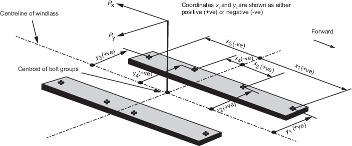
Figure 5.8.2 Direction of forces and
weight
8.14.4 The axial force Ri in bolt group (or bolt) i, positive
in tension, may be calculated from:
|
Rxi |
= |
Px h xi Ai/Ix in
kN |
|
Ryi |
= |
Py h yi Ai/Iy in
kN, and |
|
Ri |
= |
Rxi + Ryi - Rsi in kN |
where
|
Px |
= |
force acting normal to the shaft axis, in kN |
|
Py |
= |
force acting parallel to the shaft axis, either inboard or
outboard whichever gives the greater force in bolt group i, in kN |
|
h |
= |
shaft height above the windlass mounting, in cm |
|
xi, yi |
= |
x and y coordinates of bolt group i from the centroid of
all N bolt groups, positive in the direction opposite to that of the
applied force, in cm |
|
Ai |
= |
cross-sectional area of all bolts in group i, in
cm2 |
|
Ix |
= |
 for N bolt groups, in
cm4 for N bolt groups, in
cm4 |
|
Iy |
= |
 for N bolt groups, in
cm4 for N bolt groups, in
cm4 |
|
Rsi |
= |
static reaction at bolt group i, due to weight of windlass,
in kN. |
8.14.5 Shear forces Fxi, Fyi applied to the bolt group
i, and the resultant combined force Fi may be calculated from:
|
Fxi |
= |
(Px- μ g M) /N in kN |
|
Fyi |
= |
(Py- μ g M) /N in kN |
and
where
|
μ |
= |
coefficient of friction (0,5) |
|
M |
= |
mass of windlass, in tonnes |
|
g |
= |
gravity acceleration (9,81 m/sec2) |
|
N |
= |
number of bolt groups. |
8.14.6 Tensile axial stresses in the individual bolts in each bolt group i are to be
calculated. The horizontal forces Fxi and Fyi are normally to be
reacted by shear chocks. Where ‘fitted’ bolts are designed to support these shear
forces in one or both directions, the von Mises equivalent stresses in the
individual bolts are to be calculated, and compared to the stress under proof load.
Where pourable resins are incorporated in the holding down arrangements, due account
is to be taken in the calculations.
8.14.7 The safety factor against bolt proof strength is to be not less than 2,0.
8.14.8 Bolts are to be of lSO 898/1 material Grade 8.8, 10.9 or 12.9 or equivalent and are
to be pretensioned by controlled means to 70 to 90 per cent of their yield stress.
Pretensioning is to be in accordance with the manufacturer’s instructions and, in
general, pretensioning by bolt torqueing up to bolt size M30 may be used. Beyond
this, pretensioning is to be carried out by an hydraulic tensioning device and the
elongation of the bolts measured to determine pre-load. Where resin chocks are
proposed, plans and calculations are to be submitted for consideration.
8.14.9 The windlass is to be efficiently bedded and secured to the deck. The
thickness of the deck in way of the windlass is to be increased. Adequate stiffening
of the deck in way of the windlass is to be provided. The scantlings of the
supporting structure and deck are to be determined by additional calculations
applying the weight of the windlass combined with the resultant force on the seat
due to the application of the following design loads:
The allowable stresses specified in Pt 3, Ch 13, 8.12 Structural requirements associated with anchoring 8.12.2 are to be used to derive the net scantlings of the supporting
structure. The capability of the supporting structure to withstand buckling is also
to be assessed.
|