
Section
7 Consumables for use in one-side welding with temporary backing
materials
7.1 General
7.1.1 The requirements for approval of combinations including temporary backing
material, for use in one-side welding techniques, are dependent on the technique used
and which basic technique it most closely follows. The following are provided for:
-
Technique m — for manual electrode/backing combinations.
-
Technique S — for wire-gas/backing combinations used with
semi-automatic multi-run technique.
-
Technique M — for wire-flux or wire-gas in combination with backing
material (and maybe supplementary filler materials) used with an automatic
multi-run technique.
-
Technique A — as for M but using a procedure with a high heat input
rate (large bead size relative to thickness welded). This would apply to welds
made by four or less runs in 20 mm thickness, or eight or less runs in 35 mm.
7.1.2 For technique m, S or M, a single butt weld is to be made in plate of 20–25
mm thickness. For technique A, two butt welds are to be made, one in plate of the
maximum thickness recommended by the manufacturer, the other in plate of approximately
half the thickness of the first. Usually this will involve thicknesses in the region of
35–40 mm and 20–25 mm respectively.
7.1.3 A wire and gas combination approved with an argon/carbon dioxide shielding
gas where the carbon dioxide content is between 15-25 per cent is also approved for
other combinations of argon/carbon dioxide, provided the carbon dioxide content is
within the range 15-25 per cent. The range of approval is limited to ferritic
consumables in solid wire, flux cored and coated wire forms and subject to the agreement
of the consumable manufacturer and LR.
7.1.4 Any unrecognised techniques or unusual combinations will be considered for
approval subject to a test programme to be agreed based on the details of the technique
and combination which are to be submitted in advance.
7.1.6 The hydrogen potential of the backing material is to be determined using
the modified Gayley-Wooding method which expresses the total hydrogen content as water
by weight per cent. The qualifying levels are:
| To
qualify as:
|
H2O g/100g
sample
|
| H15
|
0,5
|
| H10
|
0,3
|
| H5
|
0,2
|
7.1.7 The sampling and approval of the combinations without the backing are to
follow the general requirements of Ch 11, 3 Electrodes for manual and gravity welding, Ch 11, 4 Wire-flux combinations for submerged-arc automatic welding or
Ch 11, 5 Wires and wire-gas combinations for manual, semi-automatic and automatic welding, as appropriate.
Table 11.7.1 Minimum low hydrogen approval
requirements for one-side welding with combinations including temporary backing
material
| Approval grades
|
'H' grade for m and S
techniques
|
'H' grade
for M technique
|
'H' grade
for A technique
|
| 1 (1N), 2
(2N), 3 (3N)
|
NR
|
NR
|
NR
|
| 1Y, 2Y,
3Y, 4Y
|
H15 (see Note
2)
|
NR
|
NR
|
| 2Y40 to
5Y40
|
H15
|
H15
|
NR
|
| 3Y47
|
H10
|
H10
|
H15
|
| 3Y42 to
5Y42
|
H10
|
H10
|
H15
|
| 3Y46 to
5Y46
|
H10
|
H10
|
H15
|
| 3Y50 to
5Y50
|
H10
|
H10
|
H10
|
| 3Y55 to
5Y55
|
H5
|
H5
|
H10
|
| 3Y62 to
5Y62
|
H5
|
H5
|
H5
|
| 3Y69 to
5Y69
|
H5
|
H5
|
H5
|
| 3Y89 to
4Y89
|
H5
|
H5
|
H5
|
| 3Y96 to
4Y96
|
H5
|
H5
|
H5
|
1 Ni Ni
|
H15
|
H15
|
NR
|
2  Ni Ni
|
H15
|
H15
|
NR
|
3  Ni Ni
|
H15
|
H15
|
NR
|
| 5 Ni (see Note 3)
|
NR
|
NR
|
NR
|
| 9 Ni (see Note 3)
|
NR
|
NR
|
NR
|
Note
1. NR – Not required. Approval may be
obtained when requested.
Note
2. Optional in this case. If low hydrogen
approval is not obtained, there is a limitation on the carbon
equivalent of the steel which is permitted to be welded.
Note
3. Assumes the use of an austenitic,
non-transformable, filler material.
|
7.1.8 Combinations approved with multi-run technique (m, S and M) for normal and
higher strength levels up to and including 'Y' are also considered suitable for welding
steels in the three strength levels below that for which they have been approved.
7.1.9 Combinations approved with multi-run technique (m, S and M) for strength
levels Y40 to Y50, but excluding Y47, are also considered suitable for welding steels in
two strength levels below that for which they have been approved.
7.1.10 Combinations approved with multi-run technique (m, S and M) for strength
levels Y47, Y55 and above are also considered suitable for welding steels in only one
strength level below that for which they have been approved.
7.1.11 Combinations approved with multi-run technique (m, S and M) for strength level Y89 are
considered suitable for welding steels in only this strength level.
7.1.12 Combinations approved with multi-run technique (m, S and M) for strength level Y96 are
also considered suitable for welding steels in one strength level below that for which
they have been approved.
7.1.13 Combinations approved for the 'A' multi-run technique are not considered
suitable for welding steels of any other strength level with that technique.
7.2 Approval tests for manual (m), semi-automatic (S) and automatic
multi-run (M) techniques
7.2.1 For each
position to be approved, one butt weld assembly is to be prepared
using plates of 20 — 25 mm thickness as shown in Figure 11.7.1 Butt weld test assembly and specimens for all techniques. The grade of plate used
is to be no higher in toughness than that for which approval is required.
The strength is to be appropriate to the grade for which welding approval
is requested.
7.2.2 The thickness of test assembly may be taken as 50 mm for Y47 base
material.
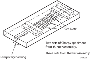
Figure 11.7.1 Butt weld test assembly and specimens for all techniques
7.2.3 The edge preparation and welding conditions are to be in accordance with
the recommendations of the manufacturers. For the m and S techniques, the assembly is to
be welded using, for the first run wire of the smallest diameter recommended by the
manufacturer and, for the remaining runs, wire of the largest diameter to be approved.
For the M technique any size wire as recommended by the manufacturer can be used.
7.2.8 Chemical
analyses are to be made and reported from positions corresponding
to the weld metal in the upper and lower Charpy specimens of the downhand
butt weld. These are to be supplied by the manufacturer and are to
include the content of all significant elements. The results of the
analysis are not to exceed the limit values specified in the standards
or by the manufacturer, the narrower tolerances being applicable in
each case.
7.3 Approval tests for high heat input automatic (A) techniques
7.3.1 Two butt
weld assemblies are to be prepared, usually one of 35–40 mm
thickness, the other 20–25 mm, as shown in Figure 11.7.1 Butt weld test assembly and specimens for all techniques, noting that in the thinner
assembly only two sets of Charpy specimens are required. The grade
of plates used is to be no higher in toughness than that for which
approval is required. The strength is to be appropriate to the grade
for which welding approval is requested.
7.3.2 For Y47
grade, the thicker assembly is to be prepared from the maximum thickness
for which approval is required, and the thinner assembly is to be
prepared from 50 mm thickness. Where approval is required for 50 mm
thickness, only one assembly from that thickness is required.
7.3.3 The edge preparation and welding conditions are to be in accordance with the
manufacturer's recommendations, and are to be reported to LR. The diameters of wires are
to be in accordance with the recommendations of the manufacturer and are to be
reported.
7.3.8 Chemical
analyses are to be made and reported from positions corresponding
to the weld metal in the uppermost and lowest Charpy specimens in
the thicker plate weld. This is to be supplied by the manufacturer
and is to include the content of all significant elements. The results
of the analysis are not to exceed the limit values specified in the
standards or by the manufacturer, the narrower tolerances being applicable
in each case.
7.4 Annual tests
7.4.1 Annual tests are to consist of, at least, one butt weld test assembly, for
each technique approved, using plates of 20 to 25 mm thickness. For the Y47 grade the
thickness of plates may be taken as 50mm.
7.4.3 A hydrogen test is required for Y89 and Y96 grades.
|