
Section
3 Electrodes for manual and gravity welding
3.1 Grading
3.1.2 Approval
of an electrode will be given in conjunction with a welding technique
indicated by a suffix `m' for manual welding, `G' for gravity or contact
electrode and `p' for deep penetration electrode.
3.1.3 If the electrodes
are in compliance with the requirements of the hydrogen test given
in Ch 11, 3.4 Hydrogen test, a suffix `H15' or `H10'
or `H5' will be added to the grade mark. Table 11.3.1 Minimum low hydrogen approval
requirements for manual and gravity electrodes shows the mandatory levels of low hydrogen approval
for the various approval grades.
Table 11.3.1 Minimum low hydrogen approval
requirements for manual and gravity electrodes
| Approval grades
|
Low hydrogen grade required
|
| 1 (1N), 2
(2N), 3 (3N)
|
NR
|
| 2Y, 3Y, 4Y
|
H15 (see Note
2)
|
| 2Y40 to
5Y40
|
H15
|
| 3Y47
|
H10
|
| 3Y42 to 5Y42
|
H10
|
| 3Y46 to
5Y46
|
H10
|
| 3Y50 to 5Y50
|
H10
|
| 3Y55 to
5Y55
|
H5
|
| 3Y62 to 5Y62
|
H5
|
| 3Y69 to
5Y69
|
H5
|
| 3Y89 to
4Y89
|
H5
|
| 3Y96 to
4Y96
|
H5
|
1 Ni Ni
|
H15
|
2 Ni Ni
|
H15
|
3 Ni Ni
|
H15
|
| 5 Ni
|
NR
(see Note 3)
|
| 9 Ni
|
NR (see Note 3)
|
Note
1. NR – Not required. Approval may be
obtained when requested.
Note
2. Optional in this case. If low hydrogen
approval is not obtained, there is a limitation on the carbon
equivalent of the steel which is permitted to be welded.
Note
3. Assumes use of an austenitic,
non-transformable, filler material.
|
3.1.4 For each
strength level, electrodes which have satisfied the requirements for
a higher toughness grade are considered as complying with the requirements
for a lower grade.
3.1.5 Electrodes
approved for normal and higher strength levels up to and including
'Y' are also considered suitable for welding steels in the three strength
levels below that for which they have been approved.
3.1.6 Electrodes
approved for strength levels Y40 to Y50, but excluding Y47 are also
considered suitable for welding steels in two strength levels below
that for which they have been approved.
3.1.7 Electrodes
approved for strength levels Y47, Y55 and above are also considered
suitable for welding steels in only one strength level below that
for which they have been approved.
3.1.8 Electrodes approved for strength level Y89 are considered suitable for this strength
level only.
3.1.9 Electrodes approved for strength level Y96 are also considered suitable for welding
steels in one strength level below that for which they have been approved.
3.1.10 The welding
current used is to be within the range recommended by the manufacturer
and, where an electrode is stated to be suitable for both a.c. and
d.c., a.c. is to be used for the preparation of the test assemblies.
3.2 Deposited metal test assemblies
3.2.3 The weld
metal is to be deposited in single- or multi-run layers according
to normal practice, and the direction of deposition of each layer
is to alternate from each end of the plate, each run of weld metal
being not less than 2 mm and not more than 4 mm thick. Between each
run, the assembly is to be left in still air until it has cooled to
less than 250°C, the temperature being taken in the centre of
the weld, on the surface of the seam. After being welded, the test
assemblies are not to be subjected to any heat treatment, except in
those higher strength grades where it is considered necessary to use
the welded joint in the stress-relieved (tempered) condition. In those
cases, the code `sr' will be added to the approval grading.
3.2.4 The chemical
analysis of the deposited weld metal in each deposited metal test
assembly is to be supplied by the manufacturer and is to include the
content of all significant alloying elements. The results of the analysis
are not to exceed the limit values specified in the standards or by
the manufacturer, the narrower tolerances being applicable in each
case.
3.2.5 One tensile
and three impact test specimens are to be taken from each test assembly
as shown in Figure 11.3.1 Deposited metal test assembly. Care
is to be taken that the axis of the tensile test specimen coincides
with the centre of the weld and the mid-thickness of the plates. The
impact test specimens are to be cut perpendicular to the weld, with
their axes 10 mm from the upper surface. The notch is to be positioned
in the centre of the weld and cut in the face of the test specimen
perpendicular to the surface of the plate.
3.2.6 The results
of all tests are to comply with the requirements of Table 11.3.2 Requirements for deposited metal
tests (covered electrodes) as appropriate.
Table 11.3.2 Requirements for deposited metal
tests (covered electrodes)
| Grade (see Note 3)
|
Yield stress
N/mm2 minimum
|
Tensile strength
N/mm2
(see Note 1)
|
Elongation
on 50 mm % minimum
|
Charpy V-notch impact tests
|
| Test temperature °C
|
Average
energy
(see Note 2)
J minimum
|
| 1N, 2N, 3N
|
305
|
400 – 560
|
22
|
+20, 0, –20
|
47
|
|
|
|
|
|
|
|
| 1Y, 2Y, 3Y, 4Y
|
375
|
490 – 660
|
22
|
+20, 0, –20,
–40
|
47
|
|
|
|
|
|
|
|
| 2Y40, 3Y40, 4Y40,
5Y40
|
400
|
510 – 690
|
22
|
0, –20, –40,
–60
|
47
|
| 3Y47
|
460
|
570 – 720
|
19
|
–20
|
64
|
| 3Y40
|
400
|
510 –
690
|
22
|
–20
|
47
|
| 3Y42
|
420
|
520 –
680
|
20
|
–20
|
47
|
| 3Y46
|
460
|
540 –
720
|
20
|
–20
|
47
|
| 3Y50
|
500
|
590 –
770
|
18
|
–20
|
50
|
| 3Y55
|
550
|
640 –
820
|
18
|
–20
|
55
|
| 3Y62
|
620
|
700 –
890
|
18
|
–20
|
62
|
| 3Y69
|
690
|
770 – 940
|
17
|
–20
|
69
|
| 3Y89
|
890
|
940 –1100
|
14
|
–20
|
69
|
| 3Y96
|
960
|
980 –1150
|
13
|
–20
|
69
|
| 4Y40
|
400
|
510 –
690
|
22
|
–40
|
47
|
| 4Y42
|
420
|
520 –
680
|
20
|
–40
|
47
|
| 4Y46
|
460
|
540 –
720
|
20
|
–40
|
47
|
| 4Y50
|
500
|
590 –
770
|
18
|
–40
|
50
|
| 4Y55
|
550
|
640 –
820
|
18
|
–40
|
55
|
| 4Y62
|
620
|
700 –
890
|
18
|
–40
|
62
|
| 4Y69
|
690
|
770 – 940
|
17
|
–40
|
69
|
| 4Y89
|
890
|
940 – 1100
|
14
|
–40
|
69
|
| 4Y96
|
960
|
980 – 1150
|
13
|
–40
|
69
|
| 5Y40
|
400
|
510 –
690
|
22
|
–60
|
47
|
| 5Y42
|
420
|
520 –
680
|
20
|
–60
|
47
|
| 5Y46
|
460
|
540 –
720
|
20
|
–60
|
47
|
| 5Y50
|
500
|
590 –
770
|
18
|
–60
|
50
|
| 5Y55
|
550
|
640 –
820
|
18
|
–60
|
55
|
| 5Y62
|
620
|
700 –
890
|
18
|
–60
|
62
|
| 5Y69
|
690
|
770 – 940
|
17
|
–60
|
69
|
| 11/2Ni
|
375
|
490 –
640
|
22
|
–80
|
34
|
| 21/4Ni
|
375
|
490 –
640
|
22
|
–90
|
34
|
| 31/2Ni
|
375
|
490 –
610
|
25
|
–100
|
34
|
| 5
Ni
|
400
|
540 –
740
|
25
|
–120
|
34
|
| 9 Ni
|
400
|
640 – 790
|
25
|
–196
|
34
|
Note
1. Single values are the minimum
requirements.
|
|
|
|
|
3.3 Butt weld test assemblies
3.3.1 Butt weld
assemblies, as shown in Figure 11.3.2 Butt weld test assembly,
are to be prepared for each welding position (downhand, horizontal-vertical,
vertical-upward, vertical-downward, and overhead) for which the electrode
is recommended by the manufacturer. In the case of electrodes for
normal strength and higher strength steels (up to 355 N/mm2 minimum
specified yield strength), electrodes satisfying the requirements
for downhand and vertical-upward positions will be considered as also
complying with the requirements for the horizontal-vertical position.
In all other cases, approval for the horizontal-vertical position
will require a butt weld to be made in that position and fully tested.
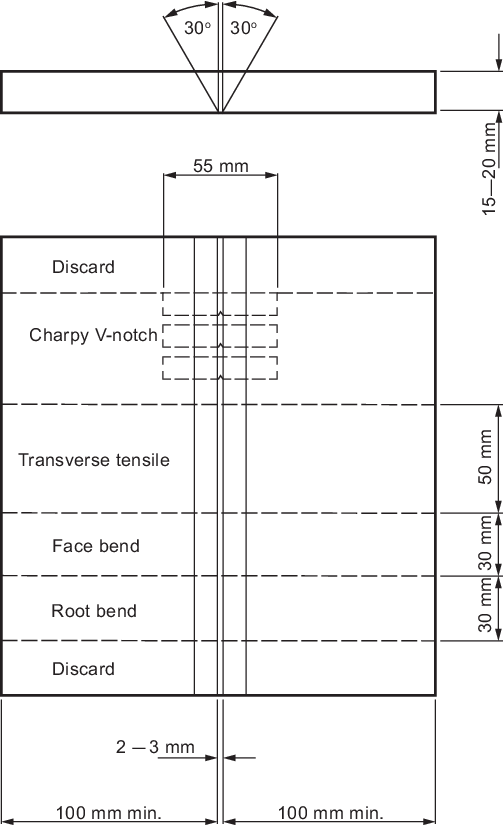
Figure 11.3.2 Butt weld test assembly
3.3.3 Where the
electrode is to be approved only in the downhand position, an additional
test assembly is to be prepared in that position.
3.3.4 The grades
of steel used for the preparation of the test assemblies are to be
as follows:
| Grade 1 (1N) electrodes
|
A
|
| Grade 2 (2N) electrodes
|
A, B or D
|
| Grade 3 3(N) electrodes
|
A, B, D or E
|
| Grade 2Y electrodes
|
AH32, AH36, DH32 or DH36
|
| Grade 3Y electrodes
|
AH32, AH36, DH32, DH36, EH32 or
EH36
|
| Grade 4Y electrodes
|
AH32
AH36, DH32, DH36,
EH32, EH36, FH32 or FH36
|
| Grade 2Y40 electrodes
|
AH40 or DH40
|
| Grade 3Y40 electrodes
|
AH40, DH40 or EH40
|
| Grade 4Y40 electrodes
|
AH40, DH40, EH40 or FH40
|
| Grade 5Y40
electrodes
|
AH40, DH40, EH40 or
FH40
|
| Grade 3Y47 electrodes
|
EH47
|
Where Grade 32 higher tensile steel
is used, the tensile strength is to be not less than 490 N/mm2.
The chemical composition, including the content of grain refining
elements, is to be reported in all cases where higher tensile steel
is used.
3.3.6 The test
assemblies are to be made by welding together two plates of equal
thickness (15 to 20 mm), not less than 100 mm in width and of sufficient
length to allow the cutting out of test specimens of the prescribed
number and size. The plate edges are to be prepared to form a single
V-joint, the included angle between the fusion faces being 60°
and the root gap 2 to 3 mm. The root face is to be 0 to 2 mm.
3.3.7 The following
welding procedure is to be adopted in making the test assemblies:
Downhand (a). The first run with 4 mm
diameter electrode. Remaining runs (except the last two layers) with
5 mm diameter electrodes or above according to the normal welding
practice with the electrodes. The runs of the last two layers with
the largest diameter of electrode manufactured or 8 mm whichever is
the lesser.
Downhand (b) (where
a second downhand test is required). First run with 4 mm diameter
electrode. Next run with an electrode of intermediate diameter of
5 mm or 6 mm, and the remaining runs with the largest diameter
of electrode manufactured or 8 mm whichever is the lesser.
Horizontal-vertical. First run with 4 mm or
5 mm diameter electrode. Subsequent runs with 5 mm diameter electrodes.
Vertical-upward and overhead. First
run with 3,25 mm diameter electrode. Remaining runs with 4 mm diameter
electrodes or possibly with 5 mm if this is recommended by the manufacturer
for the positions concerned.
Vertical-downward. If the electrode being tested is intended for vertical welding
in the downward direction, this technique is to be adopted for the
preparation of the test assembly using electrode diameters as recommended
by the manufacturer.
3.3.8 For all
assemblies, the back sealing runs are to be made with 4 mm diameter
electrodes in the welding position appropriate to each test sample,
after cutting out the root run to clean metal. For electrodes suitable
for downhand welding only, the test assemblies may be turned over
to carry out the back sealing run.
3.3.9 Normal welding
practice is to be used and, between each run, the assembly is to be
left in still air until it has cooled to less than 250°C, the
temperature being taken in the centre of the weld, on the surface
of the seam. After being welded, the test assemblies are not to be
subjected to any heat treatment, except in those higher strength grades
where it is considered necessary to use the welded joint in the stress-relieved
(tempered) condition. In those cases, the code `sr' will be added
to the approval grading.
3.3.10 It is
recommended that the welded assemblies be subjected to a radiographic
examination to ascertain if there are any defects in the weld prior
to the preparation of test specimens.
3.3.12 The results
of all tensile and impact tests are to comply with the requirements
of Table 11.3.3 Requirements for butt weld tests
(covered electrodes) as appropriate.
The position of fracture in the transverse tensile test is to be reported.
Table 11.3.3 Requirements for butt weld tests
(covered electrodes)
| Grade (see Note
3)
|
Tensile
strength
N/mm2
|
Bend test ratio:

|
Charpy V-notch impact tests
|
Test
temperature
°C
|
Average
energy
(see Note 1)
J minimum
|
All
positions
(see Note 2)
|
| 1N, 2N, 3N
|
400
|
3
|
+20, 0,
–20
|
47 (34)
|
|
|
|
|
|
|
| 1Y, 2Y, 3Y, 4Y
|
490
|
3
|
+20, 0,
–20, –40
|
47 (34)
|
|
|
|
|
|
|
| 2Y40, 3Y40, 4Y40,
5Y40
|
510
|
3
|
0, –20,
–40, –60
|
47 (39)
|
| 3Y47
|
570 - 720
|
4
|
–20
|
64
|
| 3Y40
|
510
|
3
|
–20
|
47
(39)
|
| 3Y42
|
520 –
680
|
4
|
–20
|
47
|
| 3Y46
|
540 –
720
|
4
|
–20
|
47
|
| 3Y50
|
590 –
770
|
4
|
–20
|
50
|
| 3Y55
|
640 –
820
|
5
|
–20
|
55
|
| 3Y62
|
700 –
890
|
5
|
–20
|
62
|
| 3Y69
|
770 – 940
|
5
|
–20
|
69
|
| 3Y89
|
940
|
6
|
–20
|
69
|
| 3Y96
|
980
|
7
|
–20
|
69
|
| 4Y40
|
510
|
3
|
–40
|
47
(39)
|
| 4Y42
|
520 –
680
|
4
|
–40
|
47
|
| 4Y46
|
540 –
720
|
4
|
–40
|
47
|
| 4Y50
|
590 –
770
|
4
|
–40
|
50
|
| 4Y55
|
640 –
820
|
5
|
–40
|
55
|
| 4Y62
|
700 –
890
|
5
|
–40
|
62
|
| 4Y69
|
770 – 940
|
5
|
–40
|
69
|
| 4Y89
|
940
|
6
|
–40
|
69
|
| 4Y96
|
980
|
7
|
–40
|
69
|
| 5Y40
|
510
|
3
|
–60
|
47
(39)
|
| 5Y42
|
520 –
680
|
4
|
–60
|
47
|
| 5Y46
|
540 –
720
|
4
|
–60
|
47
|
| 5Y50
|
590 –
770
|
4
|
–60
|
50
|
| 5Y55
|
640 –
820
|
5
|
–60
|
55
|
| 5Y62
|
700 –
890
|
5
|
–60
|
62
|
| 5Y69
|
770 –
940
|
5
|
–60
|
69
|
| 11/2Ni
|
490
|
3
|
–80
|
27
|
| 21/4Ni
|
490
|
3
|
-90
|
27
|
| 31/2Ni
|
490
|
3
|
–100
|
27
|
| 5
Ni
|
540
|
4
|
–120
|
27
|
| 9 Ni
|
640
|
4
|
–196
|
27
|
Note
2. Values in ( ) apply only to welds made
in the vertical position with upward progression.
|
3.3.13 The bend
test specimens can be considered as complying with the requirements
if, after bending, no crack or other open defect exceeding 3 mm in
dimensions can be seen on the outer surface.
3.4 Hydrogen test
3.4.1 The hydrogen gradings are specified in Ch 11, 3.1 Grading 3.1.3. The hydrogen grading required determines the method
of testing permitted as shown in Table 11.3.4 Permitted methods for obtaining
low hydrogen grading. Four test specimens are to be prepared and
tested, and all four hydrogen test results must be below the maximum value for the
hydrogen mark required.
Table 11.3.4 Permitted methods for obtaining
low hydrogen grading
| Hydrogen Grade
|
Permitted
Method
|
| H15
|
ISO 3690
(Mercury or Thermal Conductivity Detector Method) Or Glycerine (See
Note)
|
| H10
|
ISO 3690
(Mercury or Thermal Conductivity Detector Method)
|
| H5
|
ISO 3690 (Mercury or
Thermal Conductivity Detector Method)
|
Note ISO method preferred.
|
3.4.2 The minimum holding time at a given test temperature for Thermal Conductivity Method
should be as shown in Table 11.3.5 Temperature and minimum holding time.
Table 11.3.5 Temperature and minimum holding time
| Measuring Method
|
Test Temperature
(°C)
|
Minimum Holding
Time (h)
|
| Thermal Conductivity Method (see Note 1)
|
Gas
Chromatography
|
45
|
72
|
| 150
|
6
|
|
Note 1. The use of hot carrier gas extraction method will be specially
considered subject to verification of testing procedure to confirm that
collection and measurement of the hydrogen occurs continuously until all
the diffusible hydrogen is quantified.
|
3.5 Fillet weld test assemblies
3.5.1 Fillet weld
assemblies as shown in Figure 11.3.4 Fillet weld test assembly are
to be prepared for each welding position (horizontal-vertical, vertical-upward,
vertical-downward or overhead) for which the electrode is recommended
by the manufacturer. The grade of steel used for the test assemblies
is to be as detailed in Ch 11, 3.3 Butt weld test assemblies 3.3.4.
The length of the test assembly, L, is to be sufficient
to allow at least the deposition of the entire length of the largest
diameter electrode being tested. Where an electrode is submitted for
approval of both butt and fillet welding, approval tests are to include
the deposited metal tests as given in Ch 11, 3.2 Deposited metal test assemblies,
the butt weld tests as given in Ch 11, 3.3 Butt weld test assemblies,
and only one fillet weld test as given in subsequent paragraphs of
this sub-Section welded in the horizontal-vertical position.
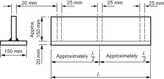
Figure 11.3.4 Fillet weld test assembly
3.5.3 The electrode
sizes to be used are the maximum and minimum diameters recommended
by the manufacturer for fillet welding. The first side is to be welded
using the maximum diameter. The second side is to be welded only after
the assembly has been allowed to cool below 50°C using the minimum
diameter. The size of these single run fillet welds will, in general,
be determined by the electrode size and the welding current employed
during testing and should represent the range of fillet weld bead
sizes recommended by the manufacturer.
3.5.4 Each test
assembly is to be sectioned to form three macro-sections, each about
25 mm thick. These are to be examined for root penetration, satisfactory
profile, freedom from cracking and reasonable freedom from porosity
and slag inclusions. Any undercut is not to exceed 0,5 mm in depth.
Convexity or concavity of the profile is not to exceed one-tenth of
the fillet bead throat dimension. All such observations are to be
reported.
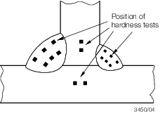
Figure 11.3.5 Hardness tests for fillet weld test assembly
3.5.6 One of the
remaining sections of the assembly is to have the weld on the first
side gouged or machined to facilitate breaking the fillet weld on
the second side by closing the two plates together, subjecting the
root of the weld to tension. On the other remaining section, the weld
on the second side is to be gouged or machined and the section fractured
using the same procedure. The fractured surfaces are to be examined.
They are to show satisfactory penetration, freedom from cracks and
reasonable freedom from porosity and this should be reported.
3.6 Electrodes designed for deep penetration welding
3.6.2 Electrodes
designed solely for the deep penetration welding technique will be
approved as complying with Grade 1 requirements only and will be given
the suffix `p'.
3.6.5 Electrodes
approved for both normal and deep penetration welding will have the
suffix 'p' added after the appropriate grade mark for normal penetration
welding.
3.6.6 Where the
manufacturer prescribes a different welding current and procedure
for the electrode when used as a deep penetration electrode and a
normal penetration electrode, the recommended current and procedure
are to be used when making the test assemblies in each case.
3.7 Deep penetration butt weld test assemblies
3.7.1 Two plates
of thickness equal to twice the diameter of the core of the electrode
plus 2 mm are to be butt welded together with one downhand run of
welding from each side. The plates are to be not less than 100 mm
wide and of sufficient length to allow the cutting out of the test
specimens of the correct number and size as shown in Figure 11.3.6 Deep penetration butt weld test
assembly. Grade A steel is to be
used for these test assemblies. The joint edges are to be prepared
square and smooth and, after tacking, the gap is not to exceed 0,25
mm. The test assembly is to be welded using an 8 mm diameter electrode,
or the largest diameter manufactured if this is less than 8 mm and
the assembly is to be allowed to cool below 50°C between runs.
3.7.4 The discards
at the end of the welded assemblies are to be not more than 35 mm
wide. The joints of these discards are to be polished and etched and
must show complete fusion and inter-penetration of the weld beads.
At each cut in the test assembly, the joints are also to be examined
to ensure that complete fusion has taken place.
3.8 Deep penetration fillet weld test assemblies
3.8.1 A fillet
weld assembly is to be prepared as shown in Figure 11.3.7 Deep penetration fillet weld test
assembly with plates about 12,5 mm in thickness. The welding
is to be carried out with one run for each fillet with plate A in
the horizontal plane during the welding operations. The length of
the fillet is to be 160 mm and the gap between the plates is to be
not more than 0,25 mm. Grade A steel is to be used for these test
assemblies.
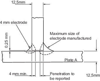
Figure 11.3.7 Deep penetration fillet weld test
assembly
3.8.2 The fillet
weld on one side of the assembly is to be carried out with a 4 mm
diameter electrode, and that on the other side with the maximum diameter
of electrode manufactured. The welding current used is to be within
the range recommended by the manufacturer, and the welding is to be
carried out using normal welding practice except that the assembly
is to be allowed to cool below 50°C between runs.
3.8.3 The welded
assembly is to be cut by sawing or machining within 35 mm of the ends
of the fillet welds, and the joints are to be polished and etched.
The welding of the fillet made with a 4 mm diameter electrode is to
show a penetration of 4 mm (see
Figure 11.3.7 Deep penetration fillet weld test
assembly) and the corresponding penetration of the fillet
made with the maximum diameter of electrode manufactured is to be
reported.
3.9 Electrodes designed for gravity or contact welding
3.9.1 Approval
for welding using the gravity, `G', technique is available for welding
only normal strength and higher tensile steels up to and including
Grade 36.
3.9.2 Where an
electrode is submitted solely for approval for use in contact welding
using automatic gravity or similar welding devices, deposited metal
tests, butt weld tests and, where appropriate, fillet weld tests similar
to those for normal manual electrodes are to be carried out using
the process for which the electrode is recommended by the manufacturer.
3.9.3 Where an
electrode is submitted for approval for use in contact welding using
automatic gravity or similar welding devices in addition to normal
manual welding, butt weld and, where appropriate, fillet weld tests,
using the gravity or other contact device as recommended by the manufacturer,
are to be carried out in addition to the normal approval tests.
3.10 Annual tests
3.10.1 For normal penetration electrodes, the annual tests are to consist of two
deposited metal test assemblies. These are to be prepared and tested in accordance with
Ch 11, 3.2 Deposited metal test assemblies. If an electrode is available in one diameter only, one test assembly
is sufficient.
3.10.4 Where an electrode is approved solely for gravity or contact welding, the
annual test is to consist of one deposited metal test assembly using the gravity or
other contact device as recommended by the manufacturer.
3.10.6 A hydrogen test is required for Y89 and Y96 grades.
|