
Section
4 Wire-flux combinations for submerged-arc automatic welding
4.1 General
4.1.1 Wire-flux combinations for single and multiple electrode submerged-arc
automatic welding, without the use of temporary backing, are divided into the following
two categories:
- For use with the multi-run technique.
- For use with the two-run technique.
Where particular wire-flux combinations are intended for welding with both
techniques, tests are to be carried out for each technique.
4.1.3 The suffixes T or M will be added after the grade mark to indicate approval
for the two-run technique or multi-run technique respectively.
4.1.4 Wire-flux combinations satisfying the requirements for multi-run or two-run
techniques will also be approved for fillet welding in the downhand and
horizontal-vertical position, subject to agreement by the manufacturer.
4.1.5 If the consumable combination is in compliance with the requirements of the
hydrogen test given in Ch 11, 3.4 Hydrogen test, a suffix H15,
H10, or H5 will be added to the grade. Table 11.4.1 Minimum low hydrogen approval
requirements for wire-flux combinations shows the mandatory levels of low hydrogen
approval for the various approval grades.
Table 11.4.1 Minimum low hydrogen approval
requirements for wire-flux combinations
| Approval grade
|
'H' grade for
Multi-run
|
'H' grade for
Two-run
|
| 1 (1N), 2
(2N), 3 (3N)
|
NR
|
NR
|
| 1Y, 2Y, 3Y,
4Y
|
NR
|
NR
|
| 2Y40 to
5Y40
|
H15
|
NR
|
| 3Y47
|
H10
|
H15
|
|
|
|
|
| 3Y42 to
5Y42
|
H10
|
H15
|
| 3Y46 to
5Y46
|
H10
|
H10
|
| 3Y50 to
5Y50
|
H10
|
H10
|
| 3Y55 to
5Y55
|
H5
|
H10
|
| 3Y62 to
5Y62
|
H5
|
H5
|
| 3Y69 to
5Y69
|
H5
|
H5
|
| 3Y89 to
4Y89
|
H5
|
H5
|
| 3Y96 to
4Y96
|
H5
|
H5
|
1 Ni Ni
|
H15
|
NR
|
2 Ni Ni
|
H15
|
NR
|
3 Ni Ni
|
H15
|
NR
|
| 5 Ni
(see Note 2)
|
NR
|
NR
|
| 9 Ni
(see Note 2)
|
NR
|
NR
|
Note
1. NR – Not required. Approval can be
obtained when requested.
Note
2. Assumes use of an austenitic,
non-transformable, filler material.
|
4.1.6 For each strength level, wire-flux combinations which have satisfied the
requirements for a higher toughness grade are considered as complying with the
requirements for a lower grade.
4.1.7 Wire-flux combinations approved with multi-run technique for normal and
higher strength levels up to and including 'Y' are also considered suitable for welding
steels in the three strength levels below that for which they have been approved.
4.1.8 Wire-flux combinations approved with multi-run technique for strength
levels Y40 to Y50, but excluding Y47 are also considered suitable for welding steels in
two strength levels below that for which they have been approved.
4.1.9 Wire-flux combinations approved with multi-run technique for strength
levels Y47, Y55 and above are also considered suitable for welding steels in only one
strength level below that for which they have been approved.
4.1.10 Wire-flux combinations approved with multi-run technique for strength level Y89 are
considered suitable for welding steels only in this strength level.
4.1.11 Wire-flux combinations approved with multi-run technique for strength level Y96 are also
considered suitable for welding steels in one strength level below that for which they
have been approved.
4.1.13 The welding current may be either a.c. or d.c. (electrode positive or
negative) according to the recommendation of the manufacturer. If both a.c. and d.c. are
recommended, a.c. is to be used for the tests.
4.1.14 Wire-flux combinations for multiple electrode submerged-arc welding will be
subject to separate approval tests. These are to be carried out generally in accordance
with the requirements of this Section.
4.1.15 Wire-flux combinations are not naturally low hydrogen in character, but for
the lower strength grades of steel low hydrogen testing is not normally a requirement
for approval. With higher strength steels it is more important and Table 11.4.1 Minimum low hydrogen approval
requirements for wire-flux combinations shows the mandatory minimum low hydrogen
status required for approval of wire-flux combinations.
4.2 Approval tests for multi-run technique
4.2.1 Where approval
for use with the multi-run technique is requested, deposited metal
and butt weld tests are to be carried out.
4.3 Deposited metal test assemblies (multi-run technique)
4.3.3 The bevelling
of the plate edges is to be carried out by machining or mechanised
gas cutting. In the latter case any remaining scale is to be removed
from the bevelled edges.
4.3.4 Welding
is to be in the downhand position, and the direction of deposition
of each run is to alternate from each end of the plate. After completion
of each run, the flux and welding slag are to be removed. Between
each run, the assembly is to be left in still air until it has cooled
to less than 250°C, the temperature being taken in the centre
of the weld, on the surface of the seam. The thickness of the layer
is to be not less than the diameter of the wire nor less than 4 mm,
unless it is clearly stated as part of the consumable manufacturer's
published recommendations.
4.3.5 The welding
conditions (amperage, voltage and rate of travel) are to be in accordance
with the recommendations of the manufacturer and are to conform with
normal good welding practice for multi-run welding.
4.3.6 The chemical
analysis of the deposited weld metal in each test assembly is to be
supplied by the manufacturer and is to include the content of all
significant alloying elements. The results of the analysis are not
to exceed the limit values specified in the standards or by the manufacturer,
the narrower tolerances being applicable in each case.
4.3.7 Two longitudinal
tensile and three impact test specimens are to be taken from each
test assembly as shown in Figure 11.4.1 Deposited metal test assembly.
Care is to be taken that the axes of the tensile test specimens coincide
with the centre of the weld and the mid-thickness of the plates. The
impact test specimens are to be cut perpendicular to the weld with
their axes 10 mm from the upper surface. The notch is to be positioned
in the centre of the weld and cut in the face of the test specimen
perpendicular to the surface of the plate.
4.3.8 In those
cases where two-run technique approval is also sought, only one longitudinal
tensile specimen need be prepared and tested from this assembly.
4.3.9 The results
of all tests are to comply with the requirements of Table 11.4.2 Requirements for deposited metal
tests (wire-flux combinations), as appropriate.
Table 11.4.2 Requirements for deposited metal
tests (wire-flux combinations)
| Grade
|
Yield stress N/mm2
minimum
|
Tensile strength N/mm2
|
Elongation on 50 mm %
minimum
|
Charpy V-notch impact tests
|
| Test temperature
°C
|
Average energy
(see Note) J minimum
|
| 1N, 2N, 3N
|
305
|
400 – 560
|
22
|
+20, 0, –20
|
34
|
| 1Y, 2Y,
3Y, 4Y
|
375
|
490 –
660
|
22
|
+20, 0,
–20, –40
|
34
|
| 2Y40, 3Y40, 4Y40,
5Y40
|
400
|
510 – 690
|
22
|
0, –20, –40,
–60
|
39
|
| 3Y47
|
460
|
570 – 720
|
19
|
–20
|
64
|
| 3Y40
|
400
|
510 –
690
|
22
|
–20
|
39
|
| 3Y42
|
420
|
520 –
680
|
20
|
–20
|
47
|
| 3Y46
|
460
|
540 –
720
|
20
|
–20
|
47
|
| 3Y50
|
500
|
590 –
770
|
18
|
–20
|
50
|
| 3Y55
|
550
|
640 –
820
|
18
|
–20
|
55
|
| 3Y62
|
620
|
700 –
890
|
18
|
–20
|
62
|
| 3Y69
|
690
|
770 –
940
|
17
|
–20
|
69
|
| 3Y89
|
890
|
940 –
1100
|
14
|
–20
|
69
|
| 3Y96
|
960
|
980 -
1150
|
13
|
–20
|
69
|
| 4Y40
|
400
|
510 – 690
|
22
|
–40
|
39
|
| 4Y42
|
420
|
520 –
680
|
20
|
–40
|
47
|
| 4Y46
|
460
|
540 –
720
|
20
|
–40
|
47
|
| 4Y50
|
500
|
590 –
770
|
18
|
–40
|
50
|
| 4Y55
|
550
|
640 –
830
|
18
|
–40
|
55
|
| 4Y62
|
620
|
700 –
890
|
18
|
–40
|
62
|
| 4Y69
|
690
|
770 – 940
|
17
|
–40
|
69
|
| 4Y89
|
890
|
940 – 1100
|
14
|
–40
|
69
|
|
|
|
980 - 1150
|
13
|
–40
|
69
|
| 5Y40
|
400
|
510 –
690
|
22
|
–60
|
39
|
| 5Y42
|
420
|
520 –
680
|
20
|
–60
|
47
|
| 5Y46
|
460
|
540 –
720
|
20
|
–60
|
47
|
| 5Y50
|
500
|
590 –
770
|
18
|
–60
|
50
|
| 5Y55
|
550
|
640 –
820
|
18
|
–60
|
55
|
| 5Y62
|
620
|
700 –
890
|
18
|
–60
|
62
|
| 5Y69
|
690
|
770 –
940
|
17
|
–60
|
69
|
| 11/2Ni
|
375
|
490-640
|
22
|
–80
|
34
|
| 21/4Ni
|
375
|
490-640
|
22
|
-90
|
34
|
| 31/2Ni
|
375
|
490 -
610
|
25
|
–100
|
34
|
| 5
Ni
|
400
|
540-740
|
25
|
–120
|
34
|
| 9 Ni
|
400
|
640-790
|
25
|
–196
|
34
|
|
|
4.4 Butt weld test assemblies (multi-run technique)
4.4.2 The grade
of steel used for the preparation of the test assembly are to be as
follows:
| Grade 1 wire-flux combination
|
A
|
| Grade 2 wire-flux
combinations
|
A, B or D
|
| Grade 3 wire-flux combinations
|
A, B, D or E
|
| Grade 1Y wire-flux
combination
|
AH32 or AH36
|
| Grade 2Y wire-flux
combinations
|
AH32, AH36, DH32 or DH36
|
| Grade 3Y wire-flux
combinations
|
AH32, AH36, DH32, DH36, EH32 or
EH36
|
| Grade 4Y wire-flux
combinations
|
AH32, AH36, DH32, DH36, EH32, EH36,
FH32 or FH36
|
| Grade 2Y40 wire-flux
combination
|
AH40 or DH40
|
| Grade 3Y40 wire-flux
combinations
|
AH40, DH40 or EH40
|
| Grade 4Y40 wire-flux
combinations
|
AH40, DH40, EH40 or FH40
|
| Grade 5Y40 wire-flux
combinations
|
AH40, DH40, EH40 or
FH40
|
| Grade 3Y47 wire-flux
combinations
|
EH47
|
Where Grade 32 higher tensile steel
is used, the tensile strength is to be not less than 490 N/mm2.
The chemical composition, including the content of grain refining
elements, is to be reported in all cases where higher tensile steel
is used.
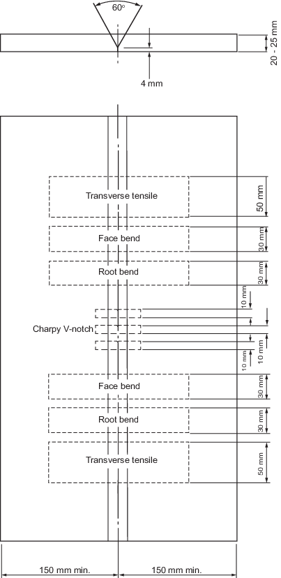
Figure 11.4.2 Butt weld test assembly (multi-run technique)
4.4.4 The plate
edges are to be prepared to form a single V-joint, the included angle
between the fusion faces being 60° and the root face being 4 mm.
The bevelling of the plate edges is to be carried out by machining
or mechanised gas cutting. In the latter case, any remaining scale
is to be removed from bevelled edges.
4.4.5 Welding
is to be carried out in the downhand position by the multi-run technique,
and the welding conditions are to be the same as those adopted for
the deposited metal test assembly. The back sealing run is to be applied
in the downhand position after cutting out the root run to clean metal.
4.4.6 It is recommended
that the welded assembly be subjected to a radiographic examination
to ascertain if there are any defects in the weld prior to the preparation
of test specimens.
4.4.8 The results
of all tensile and impact tests are to comply with the requirements
of Table 11.4.3 Requirements for butt weld tests
(wire-flux combinations), as appropriate.
The position of fracture of the transverse tensile test is to be reported.
Table 11.4.3 Requirements for butt weld tests
(wire-flux combinations)
| Grade
|
Tensile strength
N/mm2
|
Bend test ratio:
|
Charpy V-notch impact tests
|
| Test
temperature °C
|
Average
energy (see Notes 1 and 2) J minimum
|
| 1N, 2N, 3N
|
400
|
3
|
+20, 0,
–20
|
34
|
| 1Y, 2Y,
3Y, 4Y
|
490
|
3
|
+20, 0,
–20, –40
|
34
|
| 2Y40, 3Y40, 4Y40,
5Y40
|
510
|
3
|
0, –20,
–40, –60
|
39
|
| 3Y47
|
570 – 720
|
4
|
–20
|
64
|
| 3Y40
|
510
|
3
|
–20
|
39
|
| 3Y42
|
520 –
680
|
4
|
–20
|
47
(41)
|
| 3Y46
|
540 –
720
|
4
|
–20
|
47
|
| 3Y50
|
590 –
770
|
4
|
–20
|
50
|
| 3Y55
|
640 –
820
|
5
|
–20
|
55
|
| 3Y62
|
700 –
890
|
5
|
–20
|
62
|
| 3Y69
|
770 –
940
|
5
|
–20
|
69
|
| 3Y89
|
940
|
6
|
–20
|
69
|
| 3Y96
|
980
|
7
|
–20
|
69
|
| 4Y40
|
510
|
3
|
–40
|
39
|
| 4Y42
|
520 –
680
|
4
|
–40
|
47
(41)
|
| 4Y46
|
540 –
720
|
4
|
–40
|
47
|
| 4Y50
|
590 – 770
|
4
|
–40
|
50
|
| 4Y55
|
640 –
820
|
5
|
–40
|
55
|
| 4Y62
|
700 –
890
|
5
|
–40
|
62
|
| 4Y69
|
770 –
940
|
5
|
–40
|
69
|
| 4Y89
|
940
|
6
|
–40
|
69
|
| 4Y96
|
980
|
7
|
–40
|
69
|
| 5Y40
|
510
|
3
|
–60
|
39
|
| 5Y42
|
520 –
680
|
4
|
–60
|
47
(41)
|
| 5Y46
|
540 –
720
|
4
|
–60
|
47
|
| 5Y50
|
590 – 770
|
4
|
–60
|
50
|
| 5Y55
|
640 –
820
|
5
|
–60
|
55
|
| 5Y62
|
700 –
890
|
5
|
–60
|
62
|
| 5Y69
|
770 – 940
|
5
|
–60
|
69
|
| 11/2Ni
|
490
|
3
|
–80
|
27
|
| 21/4Ni
|
490
|
3
|
-90
|
27
|
| 31/2Ni
|
490
|
3
|
–100
|
27
|
| 5
Ni
|
540
|
4
|
–120
|
27
|
| 9 Ni
|
640
|
4
|
–196
|
27
|
Note
2. Values in ( ) apply only to two-run
technique impact test specimens.
|
4.4.9 The bend
test specimens can be considered as complying with the requirements
if, after bending, no cracks or other open defects exceeding 3 mm
in dimension can be seen on the outer surface.
4.5 Approval tests for two-run technique
4.5.1 Where approval
for use with the two-run technique is requested, two butt weld test
assemblies are to be prepared and tested using plates of the strength
level for which approval is required. Each strength level requires
separate approval.
4.5.2 Two welded
assemblies are to be made from a pair of plates of matching thicknesses.
The thickness of the thicker pair of plates will be the maximum for
which the approval is valid. The second assembly is to be welded from
plates having approximately half of the thickness of the first assembly.
4.6 Butt weld test assemblies (two-run technique)
4.6.1 The grade
of steel used for the preparation of the test assemblies is not to
be of any higher grade (impact toughness) than that for which approval
is required. The chemical composition, including the content of grain
refining elements, and the strength properties of the plates used,
are to be reported.
4.6.3 Each butt
weld is to be welded in two runs, one from each side, using amperages,
voltages and travel speeds in accordance with the recommendations
of the manufacturer and normal good welding practice. After completion
of the first run, the flux and welding slag are to be removed and
the assembly is to be left in still air until it has cooled to less
than 100°C, the temperature being taken in the centre of the weld,
on the surface of the seam.
4.6.4 It is recommended
that the butt weld assemblies be subjected to radiographic examination
to ascertain if there are any defects in the weld prior to the preparation
of test specimens.
4.6.7 The bend
test specimens can be considered as complying with the requirements
if, after bending, no crack or other open defects exceeding 3 mm in
dimensions can be seen on the outer surface. One of the specimens
from each assembly is to be tested with the side first welded in tension,
and the second specimen with the other side in tension.
4.6.9 The chemical
analysis of the weld metal of the second run in each assembly is to
be determined and reported. This is to include the content of all
significant elements. The results of the analysis are not to exceed
the limit values specified in the standards or by the manufacturer,
the narrower tolerances being applicable in each case.
4.7 Annual tests
4.7.1 Annual tests
are to consist of at least the following:
-
For wire-flux combinations approved for the multi-run technique, one
deposited metal test assembly.
-
For wire-flux combinations approved for the two-run technique, one
butt weld test assembly using plate material 20 to 25 mm in thickness. For Y47,
the thickness of plate material may be taken as 50 mm.
- A hydrogen test for Y89 and Y96 grades.
4.7.3 The butt
weld test assemblies are to be prepared and tested in accordance with Ch 11, 4.6 Butt weld test assemblies (two-run technique), except that only one transverse tensile,
two bend, three impact test specimens and a chemical analysis are
required. One longitudinal tensile test specimen is also to be prepared
where the wire-flux combination is approved solely for the two-run
technique.
4.7.4 Where a
wire-flux combination is approved for welding a range of steels with
different specified minimum strength levels, steel of the highest
strength approved is to be used for the preparation of the butt weld
assembly required by Ch 11, 4.7 Annual tests 4.7.1.(b).
|