
Section
5 Wires and wire-gas combinations for manual, semi-automatic and
automatic welding
5.1 General
5.1.1 Wire-gas
combinations and flux-cored or flux-coated wires (for use with or
without a shielding gas) are divided into the following categories
for the purposes of approval testing:
-
For use in manual
multi-run welding with the inert gas tungsten arc welding process
(GTAW).
-
For use in semi-automatic
multi-run metal arc welding.
-
For use in single
electrode multi-run automatic metal arc and GTAW welding.
-
For use in single
electrode two-run automatic metal arc and GTAW welding.
5.1.2 The term
`manual' is used to describe the technique where the gas-shielded
tungsten arc torch is held in one hand and the filler is added separately
by the other hand.
5.1.3 The term
`semi-automatic' is used to describe processes in which the weld is
made manually by a welder holding a gun through which the wire is
continuously fed.
5.1.4 In the GTAW
process, `automatic' refers to the fully mechanized control and application
of both torch and separate filler wire.
5.1.6 A suffix
S will be added after the grade mark to indicate approval for semi-automatic
multi-run welding.
5.1.7 For wires
intended for automatic welding, the suffixes T or M will be added
after the grade mark to indicate approval for two-run or multi-run
welding techniques, respectively.
5.1.8 For wires
intended for both semi-automatic and automatic welding, the suffixes
will be added in combination.
5.1.9 Solid wire-gas
combinations are considered naturally low hydrogen in character and
qualify for `H15' approval without testing. This is not so for cored
wires and continuous coated wires which must be tested if there is
a need for low hydrogen approval. For the lower strength grades of
steel, low hydrogen testing is not normally a requirement for approval.
With higher strength steels, it is more important and Table 11.5.1 Minimum low hydrogen approval
requirements for wires and wire-gas combinations shows the mandatory minimum
low hydrogen status required for approval of wire-gas combinations.
5.1.10 The testing
methods to be used for low hydrogen approval are to be in accordance
with Ch 11, 3.4 Hydrogen test, modified to use the manufacturer's
recommended welding conditions and adjusting the deposition rate to
give a weld deposit weight per sample similar to that deposited when
using manual electrodes.
5.1.11 Where
applicable, the approved combination will name either the specific
gas composition or its trade name, but in either case the composition
of the shielding gas is to be reported. Unless otherwise agreed, additional
approval tests are required when a shielding gas is used other than
that used for the original approval tests. However a wire and gas
combination approved with an argon/carbon dioxide shielding gas where
the carbon dioxide is between 15-25 per cent is also approved for
other combinations of argon/carbon dioxide, provided the carbon dioxide
content is within the range 15-25 per cent. The range of approval
is limited to ferritic consumables in solid wire, flux cored and coated
wire forms and subject to the agreement of the consumable manufacturer
and LR.
5.1.12 Wires
and wire-gas combinations for multiple electrode automatic welding
will be subject to separate approval tests. Any proposals are to be
submitted for consideration.
5.1.13 Wires
and wire-gas combinations approved with multi-run technique for normal
and higher strength levels up to and including 'Y' are also considered
suitable for welding steels in the three strength levels below that
for which they have been approved.
5.1.14 Wires
and wire-gas combinations approved with multi-run technique for strength
levels Y40 to Y50, but excluding Y47 are also considered suitable
for welding steels in two strength levels below that for which they
have been approved.
5.1.15 Wires
and wire-gas combinations approved with multi-run technique for strength
levels Y47, Y55 and above are also considered suitable for welding
steels in only one strength level below that for which they have been
approved.
5.1.16 Wires and wire-gas combinations approved with multi-run technique for strength level Y89
are considered suitable for welding steels only in this strength level.
5.1.17 Wires and wire-gas combinations approved with multi-run technique for strength level Y96
are also considered suitable for welding steels in one strength level below that for
which they have been approved.
5.1.18 Wires
and wire-gas combinations with two-run technique approval are not
considered suitable for welding steels of any other strength level
with that technique, see
Ch 11, 5.4 Approval tests for two-run automatic welding 5.4.1.
Table 11.5.1 Minimum low hydrogen approval
requirements for wires and wire-gas combinations
| Approval
grades
|
'H' grade for m and S
techniques
|
'H' grade
for M technique
|
'H' grade
for T technique
|
| 1 (1N), 2
(2N), 3 (3N)
|
NR
|
NR
|
NR
|
| 1Y, 2Y, 3Y,
4Y
|
H15
(see Note 2)
|
NR
|
NR
|
| 2Y40 to
5Y40
|
H15
|
H15
|
NR
|
| 3Y47
|
H10
|
H10
|
H10
|
| 3Y42 to 5Y42
|
H10
|
H10
|
H15
|
| 3Y46 to
5Y46
|
H10
|
H10
|
H15
|
| 3Y50 to 5Y50
|
H10
|
H10
|
H10
|
| 3Y55 to
5Y55
|
H5
|
H5
|
H10
|
| 3Y62 to 5Y62
|
H5
|
H5
|
H5
|
| 3Y69 to
5Y69
|
H5
|
H5
|
H5
|
| 3Y89 to
4Y89
|
H5
|
H5
|
H5
|
| 3Y96 to
4Y96
|
H5
|
H5
|
H5
|
1  Ni Ni
|
H15
|
H15
|
NR
|
2 Ni Ni
|
H15
|
H15
|
NR
|
3 Ni Ni
|
H15
|
H15
|
NR
|
| 5 Ni
|
NR
(see Note 3)
|
NR
|
NR
|
| 9 Ni
|
NR (see Note 3)
|
NR
|
NR
|
Note
1. NR – Not required. Approval may be
obtained when requested.
Note
2. Optional in this case. If low hydrogen
approval is not obtained, there is a limitation on the carbon
equivalent of the steel which is permitted to be welded.
Note
3. Assumes use of an austenitic,
non-transformable, filler material.
|
5.2 Approval tests for manual and semi-automatic multi-run welding
5.2.2 Two deposited
metal test assemblies are to be prepared in the downhand position
as shown in Figure 11.3.1 Deposited metal test assembly, one using
the smallest diameter, and the other using the largest diameter of
wire for which approval is required. Where only one diameter is manufactured,
only one deposited metal assembly is to be prepared.
5.2.4 The weld
metal is to be deposited according to the practice recommended by
the manufacturer, and the thickness of each layer of weld metal is
to be between 2 mm and 6 mm, unless it is clearly stated as part of
the consumable manufacturer's published recommendations.
5.2.5 The chemical
analysis of the deposited weld metal in each test assembly is to be
supplied by the manufacturer and is to include the content of all
significant alloying elements. The results of the analysis are not
to exceed the limit values specified in the standards or by the manufacturer,
the narrower tolerances being applicable in each case.
5.2.6 Butt weld
assemblies as shown in Figure 11.3.2 Butt weld test assembly are
to be prepared for each welding position for which the wire is to
be approved. In the case of approvals for normal and higher strength
steels (up to 355 N/mm2 minimum specified yield strength),
tests satisfying the requirements in both the downhand and vertical-upward
positions will be considered as having also satisfied the requirements
for the horizontal-vertical position. In all other cases, approval
in the horizontal-vertical position will require a butt weld to be
made in that position and be fully tested.
5.2.7 The downhand
assembly is to be welded using, for the first run, wire of the smallest
diameter to be approved and, for the remaining runs, wire of the largest
diameter to be approved.
5.2.8 Where approval
is requested only in the downhand position, an additional butt weld
assembly is to be prepared in that position using, if possible, wires
of different diameter from those required by Ch 11, 5.2 Approval tests for manual and semi-automatic multi-run welding 5.2.7. If only one wire diameter is to be approved, this second
downhand butt weld should be made using either larger or smaller beads
than the first assembly.
5.2.9 The butt
weld assemblies, in positions other than downhand, are to be welded
using, for the first run, wire of the smallest diameter to be approved,
and for the remaining runs, the largest diameter of wire recommended
by the manufacturer for the position concerned.
5.3 Approval tests for multi-run automatic welding
5.3.7 At the discretion
of LR, wires approved for semi-automatic welding in the downhand position
may also be approved without additional tests, for use in multi-run
automatic welding.
5.4 Approval tests for two-run automatic welding
5.4.3 If approval
is requested for welding plate thicker than 25 mm, one assembly is
to be prepared using plates approximately 20 mm in thickness and the
other using plates of the maximum thickness for which approval is
requested.
5.4.4 The edge
preparation of the test assemblies is to be as shown in Figure 11.5.1 Normal edge preparation for
two-run butt weld test assemblies. Small deviations in edge
preparation may be allowed, if these form part of the consumable manufacturer's
recommendations. For assemblies using plates over 25 mm in thickness,
the edge preparation is to be reported for information.
5.4.5 The diameters
of wires used are to be in accordance with the recommendations of
the manufacturer and are to be reported.
5.4.7 The weld
metal chemical analysis is to be reported as in Ch 11, 4.6 Butt weld test assemblies (two-run technique) 4.6.9. The results of the analysis are
not to exceed the limit values specified in the standards or by the
manufacturer, the narrower tolerances being applicable in each case.
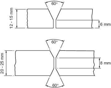
Figure 11.5.1 Normal edge preparation for
two-run butt weld test assemblies
5.5 Annual tests
|