
Section
3 Shell envelope laminate
3.1 General
3.1.1 The requirements
in respect of the general plating elements of the shell envelope,
excluding the deck, are contained within this Section.
3.2 Keel plate
3.2.1 The width, b
K, and thickness, t
K, of
plate keels are not to be taken as less than:
3.2.2 In no case
is the thickness of the keel to be less than that of the adjacent
bottom shell plating.
3.2.3 The width
and thickness of plate keels are to be maintained throughout the length
of the craft from the transom to a point not less than 25 per cent
of the freeboard measured at the forward perpendicular (FP), above
the deepest load waterline on the stem. Thereafter the keel thickness
may be reduced to that required by Pt 8, Ch 3, 3.3 Stem plate for
the stem. Laminate tapers are to be in accordance with Pt 8, Ch 2, 3.9 Laminate detail.
3.2.4 Where the
bottom shell is of sandwich construction the keel is, in general,
to be formed by locally returning to single skin construction for
a width as required by Pt 8, Ch 3, 3.2 Keel plate 3.2.1.
The Rule thickness of keel is to comprise both the inner and outer
skins of the adjacent bottom shell sandwich plus additional reinforcement
as required. The distribution of reinforcement in way of the plate
keel and sandwich bottom structure is to be in accordance with Figure 3.3.1 Single skin/sandwich skin intersection detail.
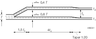
Figure 3.3.1 Single skin/sandwich skin intersection detail
3.2.5 For large
or novel craft, or yachts with externally attached ballast keels,
or where it is proposed to incorporate keels of the `bar' type the
scantlings of the keel will be specially considered.
3.3 Stem plate
3.3.1 The thickness
of the plate stem, t
s, is not to be taken
as less than that given by the following expression:
where
|
k
t
|
= |
as defined in Pt 8, Ch 3, 3.2 Keel plate 3.2.1
|
|
L
R
|
= |
Rule length, in metres, as defined in Pt 8, Ch 3, 1.5 Symbols and definitions 1.5.1
|
|
σf
|
= |
ultimate
flexural strength of the stem plate material, in N/mm2, see
Pt 8, Ch 3, 1.13 Determination of properties and stresses for single skin plate laminates 1.13.6.
|
3.3.2 In no case
is the thickness of the plate stem to be taken as less than the thickness
of the adjacent side shell plating.
3.3.4 Plate stems
are to be supported by horizontal diaphragms and, where the stem radius
is large, a centreline stiffener or web may be required.
3.3.5 Where the
side shell is of sandwich construction the stem is to be formed by
locally returning to single skin construction for a width as required
by Pt 8, Ch 3, 3.2 Keel plate 3.2.1. The Rule thickness
of stem is to comprise both the inner and outer skins of the adjacent
side shell sandwich plus additional reinforcement as required. The
distribution of reinforcement in way of the plate stem and sandwich
bottom structure is to be in accordance with Figure 3.3.1 Single skin/sandwich skin intersection detail.
3.4 Bottom
3.4.1 The bending
moment assumed to be carried by the bottom shell plating is to be
not less than that determined from Pt 8, Ch 3, 1.9 Plate and sandwich laminates 1.9.1,
using the design pressure from Pt 5, Ch 3, 3.1 Hull structures or Pt 5, Ch 4, 3.1 Hull structures for
high speed or displacement type craft as appropriate. This bending
moment is to be applied to laminates of both single skin and sandwich
construction in the determination of the panel scantling required
by Pt 8, Ch 3, 3.4 Bottom 3.4.2 and Pt 8, Ch 3, 3.4 Bottom 3.4.4 respectively.
3.4.3 In no case
is the minimum thickness of single skin plating to be taken as less
than 5,5 mm.
3.4.7 Additionally,
for high speed craft, the minimum thickness requirements for the bottom
shell between the bilge tangential points or chines and the chine
line or 150 mm above the static load waterline, whichever is the greater,
is not to be less than determined for the side shell using the side
shell impact pressure or the bottom shell hydrostatic or pitching
pressures associated with a displacement or semi-displacement type
craft whichever is the greater, see
Figure 3.3.2 Extent of bottom shell.
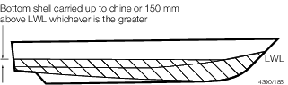
Figure 3.3.2 Extent of bottom shell
3.4.8 Special
consideration may be given to laminate thicknesses lesser than those
required by Pt 8, Ch 3, 3.4 Bottom 3.4.2 and Pt 8, Ch 3, 3.4 Bottom 3.4.4, provided that all of the structural
strength requirements of the Rules are complied with, a satisfactory
water barrier is provided, see
Pt 8, Ch 3, 2.3 Sandwich skin laminate 2.3.1, and the equivalent impact resistance is demonstrated
as required by Pt 8, Ch 3, 2.8 Impact considerations 2.8.2.
3.5 Side
3.5.1 The bending
moment assumed to be carried by the side shell plating is to be not
less than that determined from Pt 8, Ch 3, 1.9 Plate and sandwich laminates 1.9.1,
using the design pressure from Pt 5, Ch 3, 3.1 Hull structures or Pt 5, Ch 4, 3.1 Hull structures for
non-displacement or displacement craft as appropriate. This bending
moment is to be applied to laminates of both single skin and sandwich
construction in the determination of the panel scantling required
by Pt 8, Ch 3, 3.5 Side 3.5.2 and Pt 8, Ch 3, 3.5 Side 3.5.4 respectively.
3.5.3 In no case
is the minimum thickness of single skin plating to be taken as less
than 5 mm.
3.5.6 Special
consideration may be given to laminate thicknesses lesser than that
required by Pt 8, Ch 3, 3.5 Side 3.5.3 and Pt 8, Ch 3, 3.5 Side 3.5.5, provided that all of the structural
strength requirements of the Rules are complied with, a satisfactory
water barrier is provided, see
Pt 8, Ch 3, 2.3 Sandwich skin laminate 2.3.1, and the equivalent impact resistance is demonstrated
as required by Pt 8, Ch 3, 2.8 Impact considerations 2.8.2.
3.6 Sheerstrake
3.6.1 The sheerstrake,
is in general, to be taken as the side shell, locally reinforced in
way of deck/hull connection and fender attachment. The amount of local
reinforcement will be dependent upon the arrangement of structure
and the proposed service, but is not to be less than that required
by Pt 8, Ch 3, 3.14 Local reinforcement.
3.6.2 The fendering
arrangements for all craft types are the responsibility of the designers/Builders
and are outside the scope of classification.
3.6.3 Where the
pressure or impact loadings that a particular type of craft will experience
in service are considered by the Builder, or subsequent Owner, to
be not covered by, or be greater than, those indicated in Pt 5 Design and Load Criteria of the Rules, details of the loadings
together with the calculations of how these will be satisfactorily
distributed into the craft's structure, are to be submitted for consideration
with the relevant contruction plans.
3.6.4 The arrangements
indicated in Pt 8, Ch 3, 3.6 Sheerstrake 3.6.5, Pt 8, Ch 3, 3.6 Sheerstrake 3.6.6, Pt 8, Ch 3, 4.19 Fenders and reinforcement in way 4.19.5 and Pt 8, Ch 3, 4.19 Fenders and reinforcement in way 4.19.6 for pilot
and fishing craft are for the guidance of the Builder and subsequent
Owners/operators of the craft. Where the intended service for either
of these types of craft, or other types of craft which may be subject
to loadings resulting from contact with other craft, jetties or similar
loading or boarding facilities, is such that the loadings are greater
than those that can be satisfactorily distributed into the craft's
structure by the arrangements indicated, the strengthening arrangements
are to be increased accordingly.
3.6.5 For pilot
craft and other general workboats which may be subject to repeated
impact loadings from contact with other craft, etc. the sheerstrake
laminate and stiffening arrangements in way are to be increased locally.
An increase in laminate weight of not less than 50 per cent of the
side shell laminate weight is to be fitted, extending in general from
the bow aft over a distance of 0,33L
R or 500
mm aft of the point at which the craft reaches its greatest breadth,
whichever is the greater, and around the quarters. The additional
weight is to extend forward of the quarter and over the transom for
a distance of 0,075L
R or 1,0 m, whichever
is the greater. This reinforcement is in general to extend from the
deck edge to below the first longitudinal stiffener, or a vertical
distance equivalent to 1/3 the freeboard height, whichever is the
greater. The additional laminate weight is then to be tapered out
to the side shell laminate weight in accordance with the Rules, see
Pt 8, Ch 3, 3.14 Local reinforcement 3.14.2. For increase
in stiffening arrangements, see
Pt 8, Ch 3, 4.19 Fenders and reinforcement in way. Where the side shell is of sandwich construction then
in way of the sheerstrake the two skins of the sandwich are to combine
and form a single skin. The weight of this single skin is to be the
Rule single skin reinforced in accordance with the above or 1,5 times
the total sandwich skin laminate weight whichever is the greater.
The arrangement and distribution of this additional laminate between
the skins in way of the taper is to be in accordance with Pt 8, Ch 3, 3.2 Keel plate 3.2.4. Where fendering can be considered
to act as a chine/spray rail the extent of bottom shell laminate is,
in general, to be to above the lower fender.
3.6.6
Fishing
craft are, in general, to have their shell laminate as required
to satisfy the Rule loadings, increased by 20 per cent. Additionally
the side shell is not to be taken as less than the bottom shell weight,
and where there are gallows, gantries, nets, or lines etc. the laminate
in way is to be further increased locally and/or suitably protected
by sheathing in timber, steel or other means. Where the hull is of
sandwich construction in way of the sheerstrake the laminate is to
combine to form a single skin as indicated in Pt 8, Ch 3, 3.6 Sheerstrake 3.6.2.
3.6.7 Individual
consideration will be given to lesser scantlings than those required
by Pt 8, Ch 3, 3.6 Sheerstrake 3.6.3 for fishing craft used
for pleasure, light duties, etc. Details of the service are to be
submitted for appraisal.
3.7 Transom boundary reinforcement
3.7.1 Additional
reinforcement is to be moulded into the transom boundary.
3.7.2 For single
skin construction, the total weight of reinforcement is to be not
less than twice the weight of the adjacent side shell plate laminate,
but need not be greater than Rule keel weight as required by Pt 8, Ch 3, 3.2 Keel plate.
3.8 Chine reinforcement
3.8.1 Additional
reinforcement is to be moulded into the chine line knuckle boundary,
chines and other areas where there is a change of section.
3.8.3 Chine details
are to be such that the continuity of structural strength across the
panel is maintained. Details of all chines are to submitted for consideration, see also LR's Guidance Notes for Structural Details.
3.9 Skeg
3.9.1 The thickness
of the skeg plating is, in general, to be not less than the thickness
of the keel at bottom or 1,5 times the thickness of the bottom shell
on the sides, whichever is the greater, see also
Pt 8, Ch 3, 5.10 Skeg construction.
3.10 Shell openings
3.10.1 Openings
are to have smooth edges and well rounded corners. Exposed edges in
way of cut-outs in single skin/plate laminate are, in general, to
be suitably sealed over laminating with not less than 2 x 450 g/m2 CSM
(or equivalent) reinforcements. Alternative arrangements demonstrating
the equivalent protection to the ingress of moisture into the laminate
will be individually considered in association provided on the relevant
plans.
3.10.2 The exposed
edges of all openings cut in sandwich panels are to be suitably sealed.
In general a high density foam core (or equivalent material) is to
be used around the perimeter of such openings. Exposed edges in way
of cut-outs in sandwich panels are to be overlaminated with a weight
of laminate not less than that required for the outer skin of the
sandwich panel.
3.10.4 Sea inlet
boxes are to have well rounded corners and, so far as possible are
to be kept clear of the bilge radius. Arrangements are to be made
to maintain the continuity of structural strength in way of the openings.
3.11 Appendages
3.11.1 The scantlings
of appendages will be subject to special consideration on the basis
of the Rules and the design loadings anticipated, but are in no case
to be taken as less than that of the surrounding structure.
3.12 Fin and tuck
3.12.1 Additional
reinforcement is to be moulded into the fin and tuck areas of yachts
which have either internal fixed ballast or external attached ballast
keels, see also
Pt 16 Control and Electrical Engineering.
3.12.2 For single
skin construction the total weight of reinforcement is not to be less
than 1,50 times the weight of the adjacent bottom shell plate laminate,
but need not be greater than the Rule keel weight as required by Pt 8, Ch 3, 3.2 Keel plate.
3.13 Transom
3.13.1 The thickness
of the stern or transom is to be not less than that required by Pt 8, Ch 3, 3.4 Bottom and Pt 8, Ch 3, 3.5 Side as
appropriate. Where water jet or sterndrive units are fitted, the scantlings
of the plating in way of the nozzles and connections will be specially
considered.
3.14 Local reinforcement
3.14.1 The hull
and deck are to be locally increased in thickness in way of fittings
for rudder tubes, propeller brackets, passenger routes, vehicle lanes,
etc. The amount of increase is to be not less than 50 per cent of
the adjacent plate laminate. Details of such reinforcement are to
be submitted.
3.14.2 Local
reinforcement is in general to extend under the adjacent supporting
structure and then be tapered gradually to the base laminate thickness
over a distance of not less than 20 times the difference in thickness, see
Figure 3.3.3 Arrangement of local reinforcement.
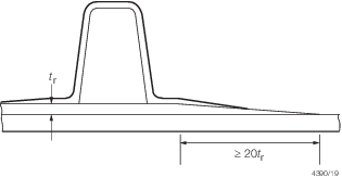
Figure 3.3.3 Arrangement of local reinforcement
3.14.3 The amount
of material laid ‘wet on wet’ is to be limited to avoid
excessive heat generation.
3.15 Hull laminate arrangement
3.15.1 The hulls
of all craft with a service speed of 25 knots or greater are to be
moulded, such that following local impact, damage progressive stripping
of surface reinforcements will not occur. This may be achieved by
arranging all hull reinforcements as shown in Figure 3.3.4 Arrangement of hull reinforcement.

Figure 3.3.4 Arrangement of hull reinforcement
3.15.2 Details
of the laminate sequence and direction of orientation are to be indicated
in the laminate schedule as required by Pt 8, Ch 2, 3.3 Laminating 3.3.7.
3.15.3 It is
recommended that woven reinforcements be laid transversely to minimise
the susceptibility to progressive stripping of hull laminates following
local impact.
3.15.4 Special
consideration is to be given to hull laminates where high glass content
is proposed and where orthophthalic resins are used.
3.16 Novel features
3.16.1 Where
the Rules do not specifically define the requirements for novel features
then the scantlings and arrangements are to be determined by direct
calculations. Such calculations are to be carried out on the basis
of the Rules, recognised standards and good practice, and are to be
submitted for appraisal.
|