
Section
5 Single bottom structure and appendages
5.1 General
5.1.1 The requirements
of this Section provide for single bottom construction of mono-hull
craft in association with either transverse or longitudinal framing.
5.1.2 All girders
are to extend as far forward and aft as practicable and care is to
be taken to avoid any abrupt discontinuity particularly in way of
skegs. Where girders are cut at bulkheads, their longitudinal strength
is to be maintained.
5.1.3 Particular
attention is to be taken to ensure that the continuity of structural
strength in way of the intersection of transverse floors and longitudinal
girders is maintained. The face reinforcement of such stiffening members
is to be effectively continuous.
5.1.4 The single
bottom structure in way of the keel, skeg and girders is to be sufficient
to withstand the forces imposed by dry-docking the craft.
5.2 Centreline girder
5.2.1 In craft
with single bottoms, a centreline girder is, in general, to be fitted
in association with transverse frames, transverses supporting longitudinals
or where the breadth of floors at the upper edge is greater than 1,5
m.
5.2.2 Centreline
girders may be in the form of intercostal or continuous top hat or
plate webs. Where the girder is intercostal, additional bracketing
and local reinforcement as given in Pt 8, Ch 3, 3.14 Local reinforcement are
to be provided to maintain the continuity of structural strength.
The face reinforcement in all cases is to be continuous.
5.2.3 The web
depth of the centre girder in general is to be equal to the depth
of the floors at the centreline as specified in Pt 8, Ch 3, 5.4 Floors, general.
5.2.8 The face
thickness, t
f, is to be not less than the
web thickness of the centre girder.
5.3 Side girders
5.3.1 Where the
floor breadth at the upper edge exceeds 6,0 m, side girders are to
be fitted at each side of the centre girder such that the spacing
between the side and centre girders or between the side girders themselves
is not greater than 3 m. Side girders, where fitted, are to extend
as far forward and aft as practicable and are, in general, to terminate
in way of bulkheads, deep floors or other primary transverse structure.
5.3.2 In the
engine room, additional side girders are generally to be fitted in
way of the main machinery.
5.3.4 The face
thickness, t
f, is not, in general, to be less
than the web thickness of the side girder.
5.4 Floors, general
5.4.1 In transversely
framed craft, floors are generally to be fitted at every frame and
underneath each bulkhead.
5.4.2 In longitudinally
framed craft, floors are to be fitted at every transverse web frame
and bulkhead and generally at a spacing not exceeding 2 m. Additional
transverse floors or webs are, in general, to be fitted at half web-frame
spacing in way of engine seatings and thrust bearings, pillars, skegs,
ballast/bilge keels and the bottom of the craft in the forefoot region.
5.4.3 The overall
depth of transverse floors at the centreline, d
f,
is not to be taken as less than:
| when B < 10 m
|
d
f =40 (B + 0,85D) mm
|
| when B ≥ 10 m
|
d
f = 40 (1,5B + 0,85D) - 200 mm
|
where B is as defined
in Pt 8, Ch 3, 1.5 Symbols and definitions 1.5.1.
5.4.6 If side
frames are attached to the floors by brackets, the depth of floor
may be reduced by 15 per cent and the floor thickness determined using
the reduced depth. The brackets are to have the same thickness as
the floors, and their arm lengths clear of the frame are to be the
same as the reduced floor depth given above.
5.4.8 The thickness
of the face reinforcement, t
f, is to be not
less than the web thickness.
5.4.10 Floors
are generally to be continuous from side to side.
5.4.11 The tops
of floors, in general, may be level from side to side. However, in
craft having considerable rise of floor the depth of the floor plate
may require to be increased to maintain the required mechanical properties
of the section.
5.4.12 The floors in the aft peak are to extend over and provide efficient support
to the sterntube where applicable.
5.5 Floors in machinery spaces
5.5.2 The depth
and mechanical properties of floors between engine or gearbox girders
is to be not less than that required to maintain continuity of structural
integrity or 50 per cent of the depth given in Pt 8, Ch 3, 5.4 Floors, general 5.4.3. The web thickness and face reinforcement
weight of such reduced height floors are to be increased appropriately
in order to maintain the continuity of structural strength.
5.6 Machinery seating
5.6.2 Main and
auxiliary engines are to be effectively secured to the hull structure
by seatings of adequate scantlings to resist the gravitational thrust,
torque and vibration forces which may be imposed upon them.
5.6.3 The longitudinal
girders forming the engine seating are to extend as far forward and
aft as is practicable and are to be adequately supported by transverse
floors or brackets.
5.6.4 Where stiffening
is of plate construction, engine holding-down bolts are to be arranged
as near as practicable to floors and longitudinal girders. When this
cannot be achieved, bracket floors are to be fitted.
5.7 Drainage arrangements
5.7.2 Sufficient
limber holes are to be positioned in the internal bottom structure
to allow for the drainage of water from all parts of the bilge to
the pump suctions.
5.7.3 Particular
attention is to be given to the positioning of limbers to ensure adequate
drainage and to avoid stress concentrations. See LR's Guidance Notes for Calculation Procedures for Composite Construction.
5.7.4 Openings
in the webs of stiffening sections, baffle plates, etc. are, in general,
to be formed by moulded-in preforms under top hat type stiffening.
Edges of openings in plate laminates are to be suitably sealed in
accordance with Pt 8, Ch 3, 1.30 Openings in the webs of stiffening members.
5.8 Rudder horns
5.8.1 The scantlings
of the rudder horn will be specially considered and in the case of
high aspect ratio or novel designs direct calculations will be required
to be submitted in accordance with Pt 3, Ch 1, 2 Direct calculations.
5.9 Sternframes
5.9.1 Where it
is proposed to mould a composite sternframe, the scantlings and arrangements
will be specially considered on the basis of direct calculations and
loadings submitted by the Builders and designers.
5.10 Skeg construction
5.10.1 Skegs
are to be effectively integrated into the adjacent structure and their
design is to be such as to facilitate this, see also
Pt 8, Ch 3, 3.9 Skeg.
5.10.2 The scantlings
of skegs and the internal diaphragms at bulkheads and web frames are
to be sufficient to withstand any docking forces to which they may
be subjected.
5.11 Forefoot and stem
5.11.1 For craft
of composite sandwich construction the forefoot region is to be so
designed that in the event of local impact (see also
Pt 8, Ch 3, 2.8 Impact considerations) with floating debris, the resultant
damage will be limited. This may be achieved by:
-
Arranging the individual
plies of the laminate such that any delamination will be directed
to the outer surface of the laminate, see
Figure 3.5.1 Arrangement of laminate in way of forefoot and stem.
-
The addition of
a sacrificial `nose', see
Figure 3.5.2 `Sacrificial nose'.
-
By the addition
of suitable sheathing, in accordance with Pt 8, Ch 3, 2.9 Sheathing.
-
For vessels where
the operating high speed waterline results in the exposure of the
forefoot region, the laminate sequence in the keel area will be specially
considered.
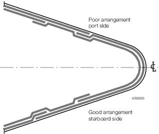
Figure 3.5.1 Arrangement of laminate in way of forefoot and stem
5.12 Transom knee
5.12.1 Centre
and side girders are to be bracketed to the transom framing members
by means of substantial knees. The face flat area of the girders may
be gradually reduced to that of the transom stiffening member in accordance
with Figure 3.5.3 Transom knee.
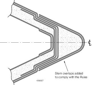
Figure 3.5.2 `Sacrificial nose'
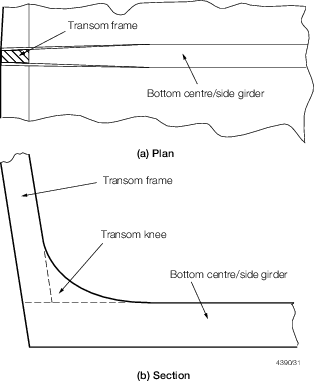
Figure 3.5.3 Transom knee
5.12.2 Hard
spots are to be avoided in way of the end connection, and care taken
to ensure that the stiffening member to which the transom knee is
bracketed can satisfactorily carry the transmitted bending moment.
|