
Section
7 Portlights, windows and viewing ports, skylights and glass walls
7.1 General
7.1.1 This Section
gives the requirements for portlights, windows, viewing ports, sliding
glass doors, glass walls, skylights, glazing materials, deadlights
and storm covers.
7.1.2 Side scuttles
and portholes are considered to be portlights.
7.1.3 A plan
showing the location of portlights, windows, viewing ports, skylights
and glass walls is to be submitted.
7.1.4 Portlights
and windows, together with their glazing and deadlights if required,
are to be of an approved design or in accordance with a recognised
National or International Standard.
7.1.5 Monolithic glass panels are to be thermally toughened safety glass.
Laminated glass panels can be made of annealed glass, heat strengthened glass,
chemically strengthened glass or thermally toughened safety glass.
7.1.6 Where consideration is given to the use of glazing materials other than
thermally toughened glass, the thickness and arrangements are to take account of any
different material properties in accordance with a recognised National or International
Standard and are to be individually approved and tested as appropriate or be in
accordance with LR’s Type Approval Procedure.
7.1.7 The use
of rubber frames is not generally acceptable.
7.1.8 In position
2, cabin bulkheads and doors are considered effective between portlights
or windows and access below.
7.1.9 Side scuttles
are defined as being round or oval openings with an area not exceeding
0.16 m2. Round or oval openings having areas exceeding,
0,16 m2 shall be treated as windows.
7.1.10 Windows
are defined as being rectangular openings generally, having a radius
at each corner relative to the window size and round or oval openings
with an area exceeding 0,16 m2.
7.2 Applications
7.3 National Authority requirements
7.3.1 In addition
to the requirements of this Section, where relevant, care is to be
given to the statutory requirements of the National Authority.
7.4 Portlights
7.4.1 Portlights
are to be in accordance with a recognised National or International
Standard or of a type accepted for the respective position and having
a valid LR Type Approval certificate. Where the portlight is not type
approved, full details are to be submitted for approval in each case.
7.4.2 Portlights
may be round, elliptical or elongated and are to be of substantial
construction.
7.4.3 Portlights
are not to be fitted in machinery spaces.
7.4.4 No portlight
is to be fitted in such a position that its sill is below a line drawn
parallel to the freeboard deck at side and having its lowest point
2,5 per cent of the breadth, B, above the load waterline
corresponding to the summer freeboard (as defined in Pt 3, Ch 1, 6.2 Principal particulars 6.2.7), or 500 mm, whichever is
the greater distance, see
Figure 4.7.1 Position of portlights.
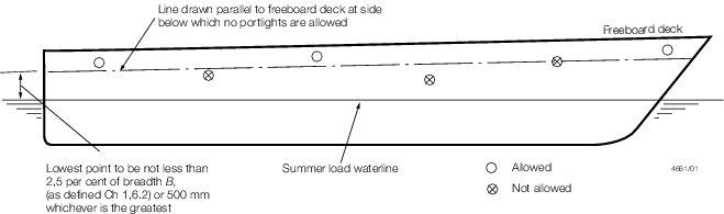
Figure 4.7.1 Position of portlights
7.5 Windows
7.5.1 Windows
are to be in accordance with a recognised National or International
Standard or of a type accepted for the respective position and having
a valid LR Type Approval certificate.
7.5.3 A hydrostatic
test is to be carried out in order to examine watertightness of windows
fitted in the side shell. A design pressure p, where p is given in Pt 3, Ch 4, 7.8 Toughened safety glass thickness 7.8.1, is
to be applied to the external face of the window and maintained for
at least 15 minutes.
7.5.4 A structural test is to be carried out in order to examine the capability of
the frame, and glazing retaining arrangements. A design pressure 4p, where
p is given in Pt 3, Ch 4, 7.8 Toughened safety glass thickness 7.8.1 is to be applied to the external face of the window,
utilising an aluminium alloy plate of appropriate temper and thickness to simulate the
flexural response in lieu of the glazing. A full-scale test with actual glazing in place
may be acceptable provided that the stresses induced are within allowable limits.
Details of the calculations made and testing procedures are to be submitted for review
prior to the test. Alternative means of demonstrating adequacy of frame, mullions and
the retaining arrangement for the glazing may be specially considered.
7.5.5 Equivalent
proposals for testing will be considered. Where alternative testing
procedures are proposed, these are to be agreed with LR before commencement.
7.5.6 Window
glazing is, in general, to be toughened safety glass, fitted in substantial
frames supporting both faces of the glass and effectively secured
to the structure. Metal to glass contact is to be avoided.
7.5.7 In general,
no windows are to be fitted in the following locations:
-
below the freeboard
deck;
-
in the first tier
end bulkheads or sides of enclosed superstructures; or
-
in first tier deckhouses
that are considered buoyant in the stability calculations.
7.5.8 Wheelhouse
window glazing is to be toughened safety glass, or where it is of
laminated or sandwich construction, the surface layers are to be of
toughened safety glass.
7.5.9 Large windows
in the aft end of superstructure or deckhouses will be specially considered.
7.5.10 Openings
in the shell for windows are to have well rounded corners.
7.6 Viewing ports
7.6.1 In general,
viewing ports are not to be fitted in the bottom shell of high speed
craft.
7.6.2 Viewing
ports are to be watertight and of substantial construction in accordance
with approved plans.
7.6.3 Glazing
is to be fitted in substantial frames supporting both faces of the
glazing and effectively secured to the hull structure.
7.6.4 Where practicable,
viewing ports are to be fitted with efficient, hinged, deadlights
which are capable of being effectively closed and secured watertight,
with or without the glazing in place.
7.6.5 Hydrostatic
pressure tests are to be carried out to confirm that the proposed
construction, when fitted in the hull, is able to withstand a pressure
of four times the design pressure and remain watertight. Where a deadlight
is fitted, this test is also to be carried out with the glazing removed
and the deadlight closed.
7.7 Sliding glass doors or `glass walls'
7.7.1 Large glass
doors or windows in the aft end of superstructures and deckhouses
and other large glass structures forming the sides, ends or roofs
of deckhouses will be specially considered.
7.7.2 When sliding
glass doors are provided, or a `glass wall' which includes an access,
an alternative access or exit from the space is to be provided and
the arrangements are to be in accordance with approved plans and weathertight
commensurate with their position. Sill heights are, in general, to
be in accordance with Pt 3, Ch 4, 6.2 External doors.
7.8 Toughened safety glass thickness
7.8.1 The thickness, t, of toughened safety glass, which is continuously
supported, i.e. on all four sides for rectangular forms and around the perimeter for
circular forms, is to be not less than 6 mm or that given by the following expression,
whichever is the greater:
for glazing of rectangular form
for glazing of circular form
where
|
r
|
= |
radius
of the glazing, in mm |
|
b
|
= |
length
of shorter side of glazing, in mm |
|
p
|
= |
design
pressure in kN/m2, as defined in Pt 5, Ch 3, 3.1 Hull structures and Pt 5, Ch 4, 3.1 Hull structures
|
|
β |
= |
– 0,17 + 0,54AR –
0,078AR2 for AR ≤ 3 |
|
|
= |
0,75 for AR > 3 |
|
AR
|
= |
aspect ratio of glazing |
|
|
= |
a/b
|
|
a
|
= |
length of longer side of glazing, in mm |
7.8.2 For glass of trapezoidal form, the length of the glazing, a, is to be
taken as the mean of the length of the longer sides. The value of b, the length
of the shorter side, may be similarly determined.
7.8.3 Alternatively, the thickness of the glass can be determined in accordance with EN 16612
or equivalent.
7.9 Laminated glass thickness
7.9.1 Where laminated toughened safety glass is used, the total thickness is to
be greater than that required for the equivalent sized glazing using toughened safety
glass. The equivalent thickness of laminated toughened safety glass,
ts, in mm, is to be determined as follows:
where
|
td
|
= |
the equivalent thickness to resist deflection, in mm, to be taken
as:  |
|
t
i
|
= |
the thickness of the glass ply, in mm |
|
t
max
|
= |
the thickness of the thickest ply in the laminate, in mm |
Note that the influence of the
interlayer is neglected, i.e. the coefficient of shear transfer has been assumed to
zero.
7.9.3 The equivalent strength and bending stiffness to that of a single,
thermally toughened pane of thickness ts, can be demonstrated in a four-point
bending test in accordance with EN 1288-3 or an equivalent recognised National or
International Standard, using no fewer than ten samples. The lower limit of the 90 per
cent confidence level interval for the laminated pane shall not be less than the same
for monolithic toughened safety glass. Comparison shall be made based on a reference
load test area per sample of 0,072 m2. When samples tested under standards
other than EN 1288-3 are smaller, the confidence level used in the statistical reduction
must be increased accordingly:
|
probability |
= |
1,0 - (1,0 - 0,90)0,072/asample |
The minimum number of samples tested must be suitably increased to get a
representative result:
where
|
asample |
= |
area of the sample between the inner rollers. |
Small scale punch test or ring-in-ring test methods shall not be used.
7.9.4 Alternatively, cross-sections of laminated glazing can be accepted on the
basis of direct calculations predicting the result of the required bending test,
see
Pt 3, Ch 4, 7.9 Laminated glass thickness 7.9.3. Direct
calculations are to be in accordance with EN 16612 Annex B or equivalent.
7.10 Other glazing materials
7.10.1 Materials
other than glass may be used for windows, except for those in the
wheelhouse, with the thickness obtained by multiplying the thickness
for toughened safety glass by a factor of 1,3 for polycarbonate and
1,5 for acrylic. Consideration will be given to composite and multi-layer
constructions where documented results of a pressure test confirm
that the proposed construction, when fitted in its appropriate frame,
is able to withstand a test pressure of four times the design pressure
and remain watertight.
7.11 Openings and framing requirements
7.11.1 The strength
and dimensions of the frame section are to be appropriate to the size
of the window, the type of glazing being used and its method of bedding.
The glazing is to be secured to its frame in accordance with the manufacturer's
instructions and recommendations; metal to glass contact is to be
avoided.
7.11.2 Rubber
frames are not acceptable for windows in Positions 1 and 2, and are
not generally acceptable in any other position in external casings.
Any proposals to fit rubber frames are to be submitted for consideration.
The proposed locations, frame dimensions, glass thicknesses and the
results of any tests carried out, are to be forwarded.
7.11.3 Where the supporting structure could be subject to deformations, the framing and
mounting system is to be selected such that the glass is isolated from these
deformations, that the integrity of the glazing is ensured and that the pane will not
detach from the frame due to either deflection or adhesive failure. This is to be
confirmed by means of a prototype test.
7.12 Deadlights and storm covers
7.12.1 Portlights
fitted to spaces below the weather deck, or to spaces within enclosed
superstructures, are to be fitted with efficient, hinged, inside deadlights
which are capable of being effectively closed and secured watertight
below the weather deck and weathertight above the weather deck.
7.12.2 In service
craft less than 24 m Rule length, L
R, and
yachts, portlights in the hull in way of accommodation may have portable
deadlights, provided that they are stored adjacent to the portlight
and can be readily fitted. Also, in the case of these craft, portlights
in superstructures or deckhouses do not require to have deadlights,
unless on the weather deck in exposed positions or protecting direct
access below, in which case, they are to be provided with deadlights
or storm covers.
7.12.3 For craft
in Service Group G1, storm covers or deadlights are generally
not required for windows or portlights in superstructures or deckhouses.
7.12.4 For craft
in Service Group G2, storm covers or deadlights are required
for:
-
50 per cent of the
windows and portlights in the front of the superstructure or deckhouse
on the weather deck.
-
The windows and
portlights in the forward half of the superstructure or deckhouse
side on the weather deck, except where these are interchangeable port
and starboard, in which case a sufficient number to fit the forward
half of one side is to be provided.
-
Each different size
of window and portlight.
7.12.5 For craft
in Service Groups G2A and G3, storm covers or deadlights
are required for:
-
All windows and
portlights in the front of the superstructure or deckhouse on the
weather deck.
-
All windows and
portlights in the sides of the superstructure or deckhouse on the
weather deck, except where they are interchangeable port and starboard,
in which case a sufficient number to fit any one side are to be provided.
-
Each different size
of window and portlight.
7.12.6 For craft
in Service Groups G4 and G5, storm covers
or deadlights are required as follows:
-
If fitted in a deckhouse
in Position 1, windows are to be provided with strong, hinged, weathertight
storm covers. However, if there is an opening leading below deck in
this deckhouse, this opening is to be treated as being on an exposed
deck and is to have weathertight protection.
-
Portlights and windows
at the shell in Position 2, protecting direct access below, are to
be provided with strong permanently attached deadlights.
-
Portlights and windows
at the shell in Position 2, not protecting direct access below, are
to be provided with strong portable steel covers for 50 per cent of
each size, with means for securing at each window.
-
Portlights and windows
set inboard from the shell in Position 2, protecting direct access
below, are either to be provided with strong permanently attached
deadlights or, where they are accessible, strong permanently attached
external storm covers instead or internal deadlights.
-
Portlights and windows
set inboard from the shell in Position 2, not protecting direct access
below, do not require deadlights or storm covers.
-
Windows in the shell,
located at least one standard height of superstructure above the lowest
Position 2 deck, are to be provided with strong portable internal
storm covers for 25 per cent of each size, with means of securing
being provided at each window.
-
Where windows are
permitted in an exposed bulkhead on the weather deck in the forward
0,25L
L, strong external storm covers are to
be provided, which may be portable and stored adjacent.
7.12.7 Deadlights
and storm covers are not required for second tier portlights or windows
in deckhouses without direct access below.
7.12.8 Where
the wheelhouse is in Position 2, in lieu of storm covers being provided
for the wheelhouse windows, a weathertight cover, fitted to a coaming
of not less than 230 mm in height around the internal stairway opening
within the wheelhouse, may be accepted. If this arrangement is accepted,
adequate means of draining the wheelhouse are to be provided.
7.12.9 If necessary,
for practical considerations, the storm covers may be in two parts.
7.12.10 Deckhouses
situated on a raised quarter deck may be treated as being in Position
2 as far as the provision of deadlights is concerned, provided the
height of the raised quarter deck is equal to, or greater than the
standard height.
7.12.11 Sliding
glass doors are to be provided with storm covers of strong construction,
or, in the case of a `glass wall', this may be protected by a strongly
constructed roller shutter or equivalent, which can be readily lowered
and secured to provide adequate protection. When necessary, additional
portable supports are to be provided for the cover. The arrangements
are to be in accordance with approved plans. Alternative arrangements
will be specially considered. In lieu of a weathertight coaming for
the cover, adequate drainage is to be provided between the cover and
the glass which may be in the form of a sump drained overboard, with
a grating over.
7.12.12 Deadlights
and storm covers are to be weathertight and of equivalent strength
to the surrounding structure.
7.12.13 Portable
deadlights and storm covers are to be clearly marked to indicate which
portlights or windows they fit and stowed in such a way as to be readily
fitted.
7.12.14 Consideration can be given to proposals to install permanent deadlights made of
tri-laminated glazing subject to agreement with the Flag Administration. The deadlights
are to have their own independent connection to the shell or bulkhead in which they are
fitted and a mechanical retaining frame is to be provided in accordance with a
recognised International Standard. Glued connections are not permitted, and the frame is
to be tested to four times the design pressure of the window. A drop test is to be
carried out in accordance with EN 356 or equivalent where a 4 kg steel ball is to be
dropped on the glass from a height of 9 metres. The test is to be repeated three times
and after each impact the glazing is to be checked for penetration by the steel ball (a
deadlight is regarded as being penetrated if the steel ball has completely passed
through the glazing). After the impact test is carried out and a positive result
achieved, the damaged deadlight is to be hydrostatically tested to 42 per cent of the
design pressure to confirm that the deadlight will retain watertightness after
damage.
7.13 Emergency exits
7.13.1 Portlights
or windows intended as emergency escapes are to be capable of being
opened from both sides and have a minimum clear opening of 600 mm
x 600 mm.
7.14 Skylights
7.14.1 Skylights,
where fitted, are to be of substantial construction and securely attached
to their coamings. The height of the lower edge of opening is to be
as required by Pt 3, Ch 4, 5.2 Coaming heights 5.2.1. The scantlings
of the coaming are to be as required by Pt 3, Ch 4, 5.3 Scantlings 5.3.2. The thickness of glazing in fixed or opening skylights is
to be appropriate to its size and position as required for portlights
or windows. Glazing in any position is to be protected from mechanical
damage, and where fitted in Positions 1 or 2 (as defined in Pt 3, Ch 1, 6.10 Position 1 and Position 2) is to be provided with robust
deadlights or storm covers permanently attached.
7.15 Testing on completion and installation
7.15.1 In order
to demonstrate that the requirements of this Section are met the closing
arrangements are to be operated under working conditions to the satisfaction
of the Surveyor.
7.16 Bonded windows and side scuttles
7.16.1 A ‘bonded
window or bonded side scuttle’ is one in which the glazing material
is secured in its frame from the outside of the ship by glue or other
adhesive material. No mechanical fixing is provided for the glazing.
Bonded windows and bonded side scuttles are to comply with the requirements
of Pt 3, Ch 4, 7.5 Windows and Pt 3, Ch 4, 7.4 Portlights respectively, in addition to the requirements in this Section.
Proposals to secure glazing from the inside of the ship are to be
specially considered using the requirements in this Section as a basis.
It should be noted that bonding from the inside is not recommended
and where it is proposed, further testing will be required. Nonload-
bearing secondary bonded glazing, e.g. glazing to improve thermal
insulation, is not required to comply with the requirements of this
sub-Section.
7.16.2 The adhesive
is to be flexible enough to support the glazing without holding it
firm. The glue strip is to be elastic, with width and thickness designed
to allow the glazing to move in both directions in the plane of the
glazing without undue forces on the bonding or the substrate. The
glass is to be free to settle under load and not be forced to follow
deflections in the supporting structure. If substantial racking of
the glazing opening under load is expected, the bonding is to be designed
to accommodate such deflections.
7.16.3 Bonded
windows and side scuttles may be considered as acceptable, in general,
on yachts, depending on their position, size of yacht and applicable
statutory requirements, noting the distinction between glazing and
the frame, which may have different requirements.
7.16.4 Bonded
windows and side scuttles are not permitted in galley areas, including
glazing in galley doors (internal or external). They are not permitted
on escape routes and evacuation routes where a fire rating is required.
The fire integrity of bulkheads is not to be impaired.
7.16.5 The failure
of laminated glass is considered to pose a lower risk to safety than
that of single pane glass. In the event of breaking, laminated glass
more readily holds together and tends not to break up into large sharp
pieces. Therefore, in general, laminated glazing is preferred. When
laminated glass is used, the sealant is to be compatible with the
interlayer. Lamination thickness is to be in accordance with Pt 3, Ch 4, 7.9 Laminated glass thickness 7.9.1. Special consideration will be
given to single pane toughened safety glass.
7.16.6 The durability
of the adhesive and the sealant in the long-term marine environment
is to be considered in the approval process. Adhesive is to be approved
in accordance with Ch 14, 2.15 Adhesive and sealant materials.
The adhesive bead is to be resistant to or protected from UV radiation,
either by an optically dense area at the edges of the glazing or by
overlapping trim or UV shielding tape. The adhesive bead is to be
resistant to or protected from fungal attack. Arrangements are to
be in accordance with the adhesive manufacturer’s published
guidelines and relevant LR Rules.
7.16.7 The edges
of the bonding recess are to be rounded to facilitate the application
of the sealant without air entrapment. The width of the gap between
the flange and the glazing is to be large enough to accommodate the
movement of the glazing as a result of hull deflection and thermal
expansion, see
Figure 4.7.2 Gap width between flange and window, bonded from the outside of the ship.
Recommended gap widths for bonded windows are to be taken as:
|
|
Gap width
|
|
Length of longest side of window
|
|
|
10–15 mm
|
|
< 1,5 m
|
|
|
15–20 mm
|
|
1,5–3,0 m
|
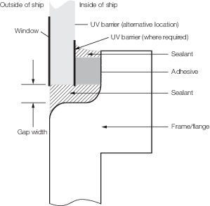
Figure 4.7.2 Gap width between flange and window, bonded from the outside of the ship
7.16.8 The minimum
adhesive width and thickness are to be in accordance with the adhesive
manufacturer’s published guidelines.
|