
Section
2 External blast
2.1 General
2.1.1 Structures
and their response to air blast loadings, can be considered to fall
into two categories:
- Diffraction-type structures.
- Drag-type structures.
2.1.2 In a
nuclear type explosion, the diffraction-type structures would be affected
mainly by diffraction loading and the drag-type structures by drag
loading.
2.1.3 Large
flat sided structures, with few openings, will respond mainly to diffraction
loading because it will take an appreciable time for the blast wave
to engulf the structure and the pressure differential between front
and rear exists during the whole of this period. A diffraction-type
structure is primarily sensitive to the peak over-pressure in the
shock wave to which it is exposed.
2.1.4 If structures
are small, or have numerous openings, the pressures on different areas
of the structure are quickly equalised; the diffraction forces operate
only for a very short time. The response of this type of structure
is then mainly due to the dynamic pressure (or drag forces) of the
blast wind. This is typical of masts and funnels. The drag loading
on the structure is determined not only by the dynamic pressure but
also by the shape of the structure. The drag coefficient is less for
rounded or streamlined structures than for irregular or sharp edged
structures.
2.1.5 The
relative importance of each type of loading in causing damage will
depend upon the type of structure as well as the characteristics of
the blast wave.
2.2 Threat level determination
2.2.2 External
blast loading can come from a variety of threats the two main ones
are far field from nuclear or fuel air type threats and near field
from detonation by close in weapon systems. This part of the Rules
is concerned only with the far field explosions.
2.2.3 The
actual threat level used in the calculation of performance and the
areas of the ship to be protected by this design method are to be
specified by the Owner and will remain confidential to LR.
2.3 Notation assessment levels and methodology
2.3.1 Design
to withstand increasing levels of blast pressure needs to employ increasing
sophistication and complexity of analysis method if the structure
is to be kept lightweight.
2.3.2 An EB1 assessment method may utilise the simple design methodology
suggested in Vol 1, Pt 4, Ch 2, 2.8 Conventional explosive pressure loads for structural
assessment. The design criteria should ensure that the structure behaves
in an elastic perfectly plastic manner with small displacements when
subjected to the proposed blast level.
2.3.3 An EB2 assessment method may utilise an extension of simple design
methodology suggested in Vol 1, Pt 4, Ch 2, 2.8 Conventional explosive pressure loads to
look at the elasto-plastic behaviour for the structural assessment.
The structure is to be designed such that maximum displacements experienced
by all structure does not compromise the structural integrity, water
or gas-tight integrity or functioning of critical items of equipment
required for operation of the ship and systems that is attached or
adjacent to the structure.
2.3.4 An EB3 assessment method should employ a failure criterion based
on an elasto-plastic methodology which considers the following structural
responses:
- Local response of the plating, here the plating can be represented
as a 2D plate strip and a large displacement, elasto-plastic dynamic
response analysis carried out using a beam-column approach.
- Local bending response of stiffened panels, the preferred model
will be to evaluate the non-linear dynamic response of a single stiffener
with an attached strip of plating modelled as a beam-column with the
appropriate boundary conditions under blast pressure.
- A lumped parameter model can be employed to look at ‘overall
sidesway’ response of a ships superstructure.
The structure is to be designed such that maximum displacements
experienced by all structure does not compromise the structural integrity,
water or gas-tight integrity or functioning of critical items of equipment
required for operation of the ship and systems that are attached or
adjacent to the structure.
2.3.5 An EB4 assessment method should employ a full non-linear analysis
using finite element methods to predict the structural response. Using
this methodology it is assumed that the ship must survive, this implies
the need to retain primary hull structural integrity, water and gas-tight
integrity or functioning of critical items of equipment required for
operation of the ship and systems that is attached or adjacent to
the structure.
2.3.6 For EB3 and EB4 notations, the assumptions made for initial
deformations are to be submitted. Where these differ for normal ship
building practice, the details are to be recorded on the approved
plan.
2.4 Definitions
2.4.1 Atmospheric
pressure P
o is to be taken as 101,3 kN/m2.
2.5 Blast pressure loads
2.5.1 For
explosions of different magnitude, the range at which the peak blast
incident and dynamic pressures occur can be scaled using the following
equation.
 where where
|
D
i
|
= |
incident distance |
|
D
n
|
= |
the distance at which the pressure occurs, in metres |
|
W |
= |
the equivalent
weight of TNT for the explosive, in kg. |
2.5.2 Similarly
for weapons of a different magnitude, the duration tp+ of
a blast can be scaled using the scaling equation
 where where
|
t
i
|
= |
incident duration |
|
t
n
|
= |
duration the pressure occurs, in seconds |
|
W
|
= |
the
equivalent weight of TNT for the explosive, in kg. |
2.5.3 When
a pressure shock front strikes a solid surface placed normal to the
direction of shock travel there is an instantaneous rise in pressure
above that of the shock front itself. The total pressure referred
to as the reflected pressure is given by:
when P
i << P
o (small charge at large stand off) P
r may
be taken as 2Pi similarly when P
i >>P
o (large charge at short range) P
r may
be taken as 8P
i
where P
i = peak blast incident over-pressure in kN/m2 from Figure 2.2.2 Blast parameters for TNT and nuclear explosions
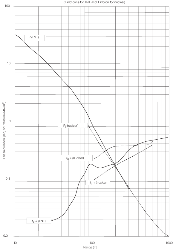
Figure 2.2.2 Blast parameters for TNT and nuclear explosions
2.5.4 The
reflected pressure, P
r can be assumed to diminish
linearly until it reaches the stagnation pressure P
s at
time t
s where
where
|
d
|
= |
is
the lesser of h or ⋉/2 in metres, see
Figure 2.2.1 Superstructure definitions
|
|
U
|
= |
shock
front velocity in m/s |
| = |

|
|
U
o
|
= |
speed of sound in air in m/s |
| = |
332+0,6T
o
|
|
T
o
|
= |
ambient air temperature in °C. |
2.5.6 The
stagnation pressure, P
s, is determined for
the front of the superstructure block by
and for the top, sides and rear by
Table 2.2.1 Drag coefficients
| Structure
|
Drag coefficient,
C
D
|
| Ship
sides
|
+1,0
|
| Front
face
|
+1,0
|
|
|
|
| Top and
sides
|
|
| 0–170
kN/m2
|
+0,4
|
| 170–340
kN/m2
|
+0,3
|
| 340–930
kN/m2
|
+0,2
|
|
|
|
| Masts and
funnels
|
+0,75
|
2.5.7 For
the top and sides of the superstructure the peak pressure will occur
at time t
t which is given by:
2.5.8 For
the rear of the superstructure the peak pressure will occur at time t
r which is given by:
2.5.9 Pressure
distributions for the faces of the superstructure block are given
in Figure 2.2.3 Pressure distribution, together with
the overall pressure acting on the block which is obtained by subtracting
the forces on the rear face from those on the front.
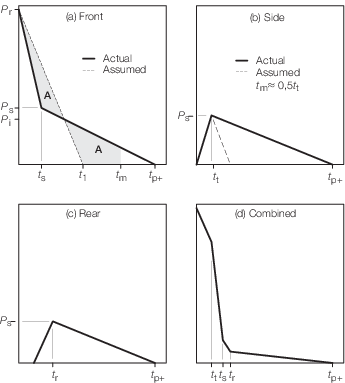
Figure 2.2.3 Pressure distribution
2.6 Nuclear threats
2.6.1 An atmospheric
nuclear explosion is most likely to occur at some height above ground
level at a location known as ground zero, which may be optimised to
produce maximum damage effects. The blast wave is reflected from the
surface and at a certain distance from ground zero, primary reflected
waves combine to form a vertical ‘mach’ front or stem
that propagates outwards from ground zero with diminishing intensity.
The peak blast incident over pressure P
i can
be determined from Vol 1, Pt 4, Ch 2, 2.3 Notation assessment levels and methodology.
2.7 Fuel air pressure loads
2.7.1 In general
a structure designed to resist a moderate degree of nuclear blast
will also have a reasonable resistance to fuel air threats and calculations
is not normally required.
2.7.2 Where
there is a risk of fuel air explosions, and for ships for which there
is no nuclear threat position required, consideration needs to be
given to the blast wave characteristics of such explosions, see
also
Vol 1, Pt 4, Ch 2, 3.1 General.
2.7.3 The
effects of temperature on the material of the structure due to fuel
air threats are to be considered using the structure surface temperature.
2.8 Conventional explosive pressure loads
2.8.1 Blast
waves caused by free field explosions in air are dependent upon the
mass shape and type of explosive, the distance from the target and
the height of the burst. As blast waves travel through air, rapid
variations occur in pressure, density, temperature and particle velocity.
2.9 Structural assessment
2.9.1 The
rules for the EB1 and EB2 structural assessment
are based on the assumption that the structure can be idealised as
a single degree of freedom system. They assume that there is no significant
loading on the superstructure or ship’s sides at the time of
the blast. In cases where there are significant lateral loadings or
concentrated point loads or fluids, the natural frequency and strength
of the structure will be specially considered.
2.9.2 The
acceptance criteria based contained in this section assume that the
structure is loaded beyond its elastic limit but not such that significant
deformations result.
2.9.3 For
plating the thickness is not to be less than:

where
|
l |
= |
the length
of the plate panel, in metres |
|
s
|
= |
width
of the panel, in mm (short span length) |
|
σo
|
= |
yield
stress of the material, N/mm2
|
|
f
p
|
= |
plate aspect ratio factor, see
Table 2.2.2 Plate factors
|
|
fσ
|
= |
stress
factor |
| = |
1,3 for σo ≤ 300 N/mm2
|
| = |
1,2 for σo > 300 N/mm2
|
|
P
p
|
= |
the peak pressure, P
r, for the front
of the superstructure, or P
s for the top sides
and rear, as defined in Vol 1, Pt 4, Ch 2, 2.5 Blast pressure loads,
in KN/m
|
|
f
DLF
|
= |
dynamic load factor to be determined from Vol 1, Pt 6, Ch 2, 5 Dynamic loading:
|
| = |
for superstructure front and ship sides using a linearly decreasing
load with initially: |
| = |
t
1 = P
r
t
s/P
s seconds
|
| = |
if t
m determined from Vol 1, Pt 6, Ch 2, 5 Dynamic loading is greater than 1,1 P
r
t
s/P
s then f
DLF, is to be recalculated such that:
|
| = |

|
| = |
For superstructure top, sides and rear using a triangular load
with: |
| = |
t
1 = 2t
t seconds
|
| = |
t
1 = 2t
r seconds
as appropriate.
|
|
|
= |
where |
|
Pr
|
= |
peak
reflected pressure as defined in Vol 1, Pt 4, Ch 2, 2.5 Blast pressure loads 2.5.3
|
|
Ps
|
= |
stagnation
pressure, as defined in Vol 1, Pt 4, Ch 2, 2.5 Blast pressure loads 2.5.6
|
|
tm
|
= |
time
at which maximum deflection occurs |
|
tp+
|
= |
positive
blast pulse duration |
|
ts
|
= |
corresponding
time at stagnation pressure, P
s.
|
Table 2.2.2 Plate factors
| Aspect ratio (A
R)
|
f
p
|
| 1,0
|
1000
|
| 0,9
|
916
|
| 0,8
|
858
|
| 0,7
|
817
|
| 0,6
|
775
|
| <0,5
|
750
|
2.9.4 The
minimum edge through thickness area of the plate is not to be less
than:
where
|
|
= |
t, σo, l, s are
given in Vol 1, Pt 4, Ch 2, 2.9 Structural assessment 2.9.3
|
|
τo
|
= |
shear
yield stress in N/mm2
|
|
P
tm
|
= |
Pressure at the time of maximum displacement, t
m,
in kN/m2 based on assumed pressure distribution.
|
|
f
p1,f
p2
|
= |
shear load factors, given in Table 2.2.3 Plate shear factors.
|
Table 2.2.3 Plate shear factors
Aspect ratios/
|
short span sides
|
long span side
|
|
|
f
p1
|
f
p2
|
f
p1
|
f
p2
|
| 1,0
|
0,18
|
0,07
|
0,18
|
0,07
|
| 0,9
|
0,16
|
0,06
|
0,20
|
0,08
|
| 0,8
|
0,14
|
0,06
|
0,22
|
0,08
|
| 0,7
|
0,13
|
0,05
|
0,24
|
0,08
|
| 0,6
|
0,11
|
0,04
|
0,26
|
0,09
|
| 0,5
|
0,09
|
0,04
|
0,28
|
0,09
|
2.9.5 The
stiffener and plate combination is considered to be satisfactory if
the plastic modulus of the beam plate combination is greater than:
where
P
p, f
DLF, f
σ and σ
o are
given in Vol 1, Pt 4, Ch 2, 2.9 Structural assessment 2.9.3
|
Z
p
|
= |
plastic section modulus of the stiffener and attached plate,
in cm3
|
 e
e
|
= |
effective
length of the beam, in metres |

|
= |
the length of the beam,
in metres |
|
fbz
|
= |
beam
support factor |
| = |
12 for fully fixed |
| = |
8 for simply supported |
|
s
|
= |
spacing
of the beams, in mm. |
2.9.6 The
maximum elastic deflection given by:
is not to be greater than
where
P
p, fDLF, s, l and l
e are given
in Vol 1, Pt 4, Ch 2, 2.9 Structural assessment 2.9.3
|
I |
= |
second
moment of inertia cm4
|
|
fbd
|
= |
beam
support factor |
| = |
384 for fully fixed |
| = |
76,8 for simply supported. |
2.9.7 The
shear area of the stiffener web is not to be less than:
where
|
|
= |
Z
p, σo, le,
l, s are given in Vol 1, Pt 4, Ch 2, 2.9 Structural assessment 2.9.3
|
|
|
= |
τo, P
tm are given in Vol 1, Pt 4, Ch 2, 2.9 Structural assessment 2.9.4
|
|
|
= |
f
s
1, f
s
2 = shear load factors, given in Table 2.2.4 Beam shear factors.
|
|
|
= |
f
b
z is given in Vol 1, Pt 4, Ch 2, 2.9 Structural assessment 2.9.5.
|
Table 2.2.4 Beam shear factors
| Beam type
|
Location
|
f
s1
|
f
s2
|
| Simply
supported
|
Both ends
|
0,39
|
0,11
|
| Fixed
ends
|
Both
ends
|
0,36
|
0,14
|
| Simple and
fixed
|
Fixed
end
|
0,43
|
0,12
|
|
|
Simple
support
|
0,26
|
0,19
|
2.9.8 Direct
calculations or analyses based on the elastoplastic or plastic response
of structure using a dynamic load factor or finite element approach
will be specially considered. The designers’ calculations are
to be submitted for approval.
2.9.9 In addition
to the assessment of plating and stiffeners, the global capability
of superstructure and above water structure are to be assessed. The
designers' calculations are to be submitted.
2.10 Design considerations
2.10.1 To
minimise the effects of external blast, protrusions from the superstructure
are to be kept to a minimum.
2.10.2 Re-entrant
corners are to be avoided, where this is impractical they are to be
covered by a blast deflecting plate, or be constructed such that the
included angle between orthogonal faces is to be as large as possible.
2.10.3 Where
the clear air gap between superstructure blocks is less than 0,1L
R, the interaction under external blast loading will be specially
considered.
|