
Section
3 Internal blast
3.1 General
3.1.1 Internal
blast is defined as that which occurs from detonation of a high explosive
from a hostile weapon or detonation of a ship’s own ammunition
inside the hull envelope. In an internal explosive loading situation
the loading on a boundary can be characterised by a series of decaying
reflected pressure waves (blast impulses) followed by the rapid formation
of a slowly decaying static pressure (Quasi static pressure QSP) as
shown in Figure 2.3.1 Typical blast pressure time history.
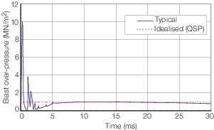
Figure 2.3.1 Typical blast pressure time history
3.1.2 The
magnitude of the initial blast impulse is related to the distance
from structure under consideration to the explosion. The reflections
are a function of the compartment geometry. The QSP is dependent on
the compartment volume with the rate of decay related to the vent
area.
3.2 Threat level determination
3.2.1 The
threat protection levels for a given vessel should be determined through
a vulnerability analysis against customer specified threat weapons.
In the absence of such a study the following levels may be used as
a guide:
- Level I Watertight bulkheads at R4N ≥
1 and zone bulkheads at R4N > 1
- Level II Watertight bulkheads at R4N ≥
1,5 and zone bulkheads at R4N > 2
- Level III Watertight bulkheads at R4N >
3 and zone bulkheads at R4N > 3
R4N is the normalised blast resistance 2,5 m high,
4 mm thick, mild steel, fillet welded bulkhead.
3.3 Notation assessment levels and methodology
3.3.1 The
Rules are aimed at limiting the spread of blast damage to compartments
adjacent to that directly affected by the explosion. For an explosion
where the ratio of charge size to compartment volume is small, it
may be possible to limit the damage to the affected compartment.
3.3.2 Ships
complying with the requirements of this section will be eligible for
the IB1 notation. Where further analysis or testing is
used to determine the blast resistance of the structure an IB2 notation
may be assigned.
3.3.3 For
the IB2 notation, the assumptions made for initial deformations
are to be submitted. Where these differ from normal ship building
practice, the details are to be recorded on the approved plan.
3.3.4 There
are specific scenarios such as fuel air explosions within aircraft
hangars where the internal blast wave characteristics will need to
be specially considered on request.
3.4 Materials
3.4.1 For
level III protection all plate bulkhead materials are
to have a sulphur content less than 0,01 per cent. This may be achieved
by the specification of through thickness properties in accordance
with the requirements of Ch 3, 8 Plates with specified through thickness properties of
Rules for Materials.
3.4.2 Consideration
should be given to the use of austenitic electrodes for fillet welding
of ferritic materials subject to high strain loading. In selecting
the filler material, consideration is to be given to the material’s
proof strength and elongation; the 0,2 per cent proof stress of the
filler material as welded is to match the strength of the ferritic
parent steel plate, and the elongation to failure is to be as great
as possible. Care should be taken to ensure that coatings are maintained
as far as practicable. Where such materials are in wet or immersed
areas, special attention is to be given to corrosion protection and
the selection of a material that is not prone to chemical or electro-chemical
attack. Details of the weld procedure are to be submitted for approval.
3.5 Quasi static pressure
3.5.1 Structural
failure can be caused by either the impulsive loading or the dynamic
loading imparted by the combined blast waves and QSP. Normally if
the weapon is sufficiently large to cause failure by impulse it will
also fail under a dynamic loading assessment based on a step function
to the QSP level. For the purposes of general design the step function
to the QSP level assessment can be used as the loading criteria to
determine failure. Safety or mission critical areas should be specially
considered.
3.5.2 The
actual threat level used in the calculation and areas of the ship
to be protected are to be specified by the Owner and will remain confidential
to LR.
3.5.3 The
QSP can be determined from the following:
|
Pqs
|
= |
2,25 (We
/V)0,72 x103 kN/m2
|
where
|
Pqs
|
= |
quasi static pressure, in kN/m2
|
|
We
|
= |
weapon equivalent weight of TNT, in kg |
|
V |
= |
free compartment
volume, in m3.
|
3.6 Structural resistance
3.6.1 The
blast resistance for a given bulkhead material, thickness and joint
style can be determined as a proportion of 2,5 m high, 4 mm thick,
mild steel, fillet welded bulkhead using the following formula based
on a combination of explosive tests and analytical techniques:
|
R
4N
|
= |
(K
j + K
m) t/
|
where
|
|
= |
R
4N is the normalised blast resistance
2,5 m high, 4 mm thick, mild steel, fillet welded bulkhead
|
|
|
= |
K
m is the material type factor, see
Table 2.3.1 Material type factor, K
m
|
|
|
= |
K
j is the joint type factor, see
Table 2.3.2 Joint type factor, K
j
|
|
|
= |
t is the thickness of steel, in metres
|
|
|
= |
 is the short span length, in metres. is the short span length, in metres.
|
Table 2.3.1 Material type factor, K
m
| Steel grade
|
K
m
|
| A, D, E, AH32, AH36
|
0
|
| DH32, EH32
|
86
|
| DH36, EH36
|
196
|
Table 2.3.2 Joint type factor, K
j
| Joint style
|
K
j
|
Note
|
| Normal fillet weld
|
625
|
Valid up for t
bh ≤ 8 mm
|
| Full penetration weld
|
665
|
Valid for t
bh ≤ 12 mm
|
| Austenitic fillet weld
|
701
|
Valid for t
bh ≤ 6 mm
|
|
Note
Values of Kj up to 1200 can be achieved using
blast resistant bulkhead designs.
|
3.6.2 The
primary mode of failure for bulkhead structures is through the edge
connection. Alternatives to the basic fillet weld have been assessed
and incorporated in the joint type factor presented in Table 2.3.2 Joint type factor, K
j
.
3.6.3 Alternative
joint types may be used but are to be categorised using a dynamic
joint test and blast assessment. For novel designs a further large
scale controlled blast test of the proposed arrangement is to be tested.
LR can provide details of the test and analysis requirements on request.
3.7 Bulkhead arrangements
3.7.1 Piping
that passes through the bulkhead is to be fitted with expansion pieces
either side of the bulkhead. In addition, piping and other penetrations
are to be arranged at the edges of the bulkhead where the relative
movement is less as shown in Figure 2.3.2 Blast bulkhead penetrations.
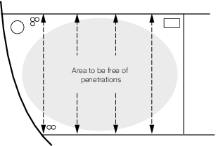
Figure 2.3.2 Blast bulkhead penetrations
3.7.2 Bulkhead
attachments are to be kept to a minimum and designed for good dynamic
performance.
3.7.3 The
strength of doors if fitted will be specially considered. Steps are
to be taken to prevent their detachment from or pushing through the
surrounding structure.
3.7.4 Consideration
should be given to the use of flexible collars around deep girder
penetrations through the blast bulkhead to allow relative movement
but retain watertight or gas-tight integrity.
3.7.5 Under
blast loading, large displacements of the bulkhead may occur. Any
nearby structure or equipment is to be located so as to provide a
minimum clearance of 350 mm from the bulkhead. This distance is generally
appropriate for deck heights of between 2 m and 3 m. The minimum clearance
for other deck heights will be specifically considered.
|
| Copyright 2022 Clasifications Register Group Limited, International Maritime Organization, International Labour Organization or Maritime
and Coastguard Agency. All rights reserved. Clasifications Register Group Limited, its affiliates and subsidiaries and their respective
officers, employees or agents are, individually and collectively, referred to in this clause as 'Clasifications Register'. Clasifications
Register assumes no responsibility and shall not be liable to any person for any loss, damage or expense caused by reliance
on the information or advice in this document or howsoever provided, unless that person has signed a contract with the relevant
Clasifications Register entity for the provision of this information or advice and in that case any responsibility or liability is
exclusively on the terms and conditions set out in that contract.
|
 |
|