
Section
2 Castings for valves, liners and bushes
2.1 Scope
2.1.1 This Section
makes provision for copper alloy castings for valves, liners, bushes
and other fittings intended for use in the construction of ships,
other marine structures, machinery and pressure piping systems.
2.1.3 As an alternative
to Ch 9, 2.1 Scope 2.1.2, castings which comply
with National or proprietary specifications may be accepted provided
that these specifications give reasonable equivalence to the requirements
of this Section or alternatively are approved for a specific application.
Generally, survey and certification are to be carried out in accordance
with the requirements of Ch 1 General Requirements.
2.2 Manufacture
2.2.1 Castings
are to be manufactured at foundries approved by LR.
2.3 Quality of castings
2.3.1 All castings
are to be free from surface or internal defects which would be prejudicial
to their proper application in service.
2.4 Chemical composition
2.4.1 The chemical
composition is to comply with the requirements of a National or International
Standard and, where appropriate, with the limits for the principal
elements of the preferred alloys listed in Table 9.2.1 Chemical compositions of long
freezing range alloys: principal elements only and Table 9.2.2 Chemical compositions of short
freezing range alloys: principal elements only.
Table 9.2.1 Chemical compositions of long
freezing range alloys: principal elements only
| Alloy
type
|
Designation
|
Chemical composition
|
Typical
applications
|
| Cu
|
Sn
|
Zn
|
Pb
|
Ni
|
P
|
| Phosphor bronze
|
Cu Sn11 P
|
87,0 –
89,5
|
10,0 –
11,5
|
0,05
max.
|
0,25
max.
|
0,10
max
|
0,5 –
1,0
|
Liners, bushes, valves and fittings
|
| Cu
Sn12
|
85,0 –
88,5
|
11,0 –
13,0
|
0,50
max.
|
0,7
max.
|
2,0
max
|
0,60
max
|
|
|
|
|
|
|
|
|
|
|
| Gunmetal
|
Cu Sn10
Zn2
|
Remainder
|
9,5 –
10,5
|
1,75 –
2,75
|
1,5
max.
|
1,0
max
|
–
|
Liners,
valves and fittings
|
|
|
|
|
|
|
|
|
|
|
| Leaded
gunmetal
|
Cu Sn5 Zn5
Pb5
|
83,0 – 87,0
|
4,0 –
6,0
|
4,0 –
6,0
|
4,0 –
6,0
|
2,0
max
|
0,10
max
|
Bushes,
valves and fittings
|
| Cu Sn7 Zn2 Pb3
|
85,0 – 89,0
|
6,0 – 8,0
|
1,5 –
3,0
|
2,5 –
3,5
|
2,0
max
|
0,10
max
|
| Cu Sn7 Zn4
Pb7
|
81,0 –
85,0
|
6,0 –
8,0
|
2,0 –
5,0
|
5,0 –
8,0
|
2,0
max
|
0,10
max
|
| Cu Sn6 Zn4
Pb2
|
86,0 –
90,0
|
5,5 –
6,5
|
3,0 –
5,0
|
1,0 –
2,0
|
1,0
max
|
0,05
max
|
|
|
|
|
|
|
|
|
|
|
| Leaded
bronze
|
Cu Sn10
Pb10
|
78,0 –
82,0
|
9,0 –
11,0
|
2,0
max.
|
8,0 –
11,0
|
2,0
max
|
0,10
max
|
Bushes
|
| Cu Sn5
Pb9
|
80,0 –
87,0
|
4,0 –
6,0
|
2,0
max.
|
8,0 –
10,0
|
2,0
max
|
0,10
max
|
| Cu Sn7
Pb15
|
74,0 –
80,0
|
6,0 –
8,0
|
2,0
max.
|
13,0 –
17,0
|
0,5 –
2,0
|
0,10
max
|
| Cu Sn5 Pb20
|
70,0 – 78,0
|
4,0– 6,0
|
2,0
max.
|
18,0 –
23,0
|
0,5 –
2,5
|
0,10
max
|
Table 9.2.2 Chemical compositions of short
freezing range alloys: principal elements only
| Alloy type
|
Designation
|
Chemical composition
|
Typical
applications
|
| Cu
|
Ni
|
Fe
|
Mn
|
Cr
|
Nb
|
Si
|
Al
|
| Copper 30%
nickel
|
Cu Ni30
Fe1 Mn1
|
64,5
min.
|
29,0–31,0
|
0,5–1,5
|
0,6–1,2
|
–
|
–
|
0,1
max.
|
–
|
Flanges, valves and fittings
|
| Cu Ni30
Fe1 Mn1 Nb Si
|
Remainder
|
29,0–31,0
|
0,5–1,5
|
0,6–1,2
|
–
|
0,5–1,0
|
0,3–0,7
|
–
|
| Cu Ni30
Cr2 Fe Mn Si (see Note)
|
Remainder
|
29,0–32,0
|
0,5–1,0
|
0,5–1,0
|
1,5–2,0
|
–
|
0,15–0,50
|
–
|
|
|
|
|
|
|
|
|
|
|
|
|
| Copper
10% nickel
|
Cu Ni10
Fe1 Mn1
|
84,5
min.
|
9,0–11,0
|
1,0–1,8
|
1,0–1,5
|
–
|
1,0
max.
|
0, 10
max.
|
–
|
Flanges,
valves and fittings
|
| Aluminium
|
Cu Al10
Fe5 Ni5
|
76,0–83,0
|
4,0–6,0
(See Note 2)
|
4,0–5,5
(See Note 2)
|
3,0
max.
|
–
|
–
|
0,1
max.
|
8,5–10,5
|
Bushes, valves and
fittings
|
| bronze
|
Cu Al11
Fe6 Ni6
|
72,0–78,0
|
4,0–7,5
(See Note 2)
|
4,0–7,0
(See Note 2)
|
2,5
max.
|
–
|
–
|
0,1
max.
|
10,0–12,0
|
Note
1. Normally alloy Cu Ni30 Cr2 Fe Mn Si
contains 0,1 to 0,25% titanium and 0,05 to 0,15% zirconium.
Note
2. For Naval ships, the nickel content is
to be higher than the iron content.
|
2.4.3 Where a cast
is wholly prepared from ingots for which an analysis is already available,
and provided that no significant alloy additions are made during melting,
the ingot maker's certified analysis can be accepted subject to occasional
check tests as requested by the Surveyor. The frequency of these check
tests should, as a minimum, be one in every ten casts. If one of these
check analyses fails to comply with the specification, checks are
to be made on the previous and subsequent melts. If one or both of
these further analyses is unsatisfactory, chemical analysis is to
be carried out on all further melts until the Surveyor is satisfied
that a return can be made to the use of occasional check tests.
2.5 Heat treatment
2.5.1 Where required
by the specification, castings may be supplied in either the `as-cast'
or heat treated condition.
2.5.2 Where castings
are supplied in a heat treated condition, the test samples are to
be heat treated with the castings they represent prior to the preparation
of the tensile test specimens.
2.6 Test material
2.6.1 Test material
sufficient for the tests specified in Ch 9, 2.6 Test material 2.6.4 and
for possible re-test purposes is to be provided for each cast of material.
2.6.2 The test
material is to be separately cast into moulds made of the same material
as that used for the castings they represent.
2.6.5 If it is
proposed to use any other form of test bar, this is to be agreed in
advance with the Surveyor.
2.6.6 As an alternative,
for liners and bushes, the test material may be taken from the ends
of the castings.
2.7 Mechanical tests
2.7.2 The results of all tests are to comply with the appropriate requirements
given in Table 9.2.3 Mechanical properties of long
freezing range alloys for acceptance purposes and Table 9.2.4 Mechanical properties of short
freezing range alloys for acceptance purposes.
Table 9.2.3 Mechanical properties of long
freezing range alloys for acceptance purposes
| Alloy type
|
Designation
|
0,2% proof stress
N/mm2
minimum
(See Note 1)
|
Tensile strength
N/mm2
minimum
|
Elongation on 5,65 % minimum % minimum
|
| Sand
|
Centrifugal
|
Sand
|
Centrifugal
|
Sand
|
Centrifugal
|
| Phosphor bronze
|
Cu Sn11
P
|
130
|
170
|
250
|
330
|
5
|
4
|
| Cu
Sn12
|
140
|
150
|
260
|
280
|
7
|
5
|
| Gunmetal
|
Cu Sn10
Zn2
|
130
|
130
|
270
|
250
|
13
|
5
|
| Leaded gunmetal
|
Cu Sn5 Zn5
Pb5
|
90
|
110
|
200
|
250
|
13
|
13
|
| Cu Sn7 Zn2
Pb3
|
130
|
130
|
230
|
260
|
14
|
12
|
| Cu Sn7 Zn4
Pb7
|
120
|
120
|
230
|
260
|
15
|
12
|
| Cu Sn6 Zn4
Pb2
|
110
|
110
|
220
|
240
|
15
|
12
|
| Leaded bronze
|
Cu Sn10
Pb10
|
80
|
110
|
180
|
220
|
8
|
6
|
| Cu Sn5
Pb9
|
60
|
90
|
160
|
200
|
7
|
6
|
| Cu Sn7
Pb15
|
80
|
90
|
170
|
200
|
8
|
7
|
| Cu Sn5
Pb20
|
70
|
80
|
150
|
170
|
5
|
6
|
Note
1. The 0,2% proof stress values are given
for information purposes only and, unless otherwise agreed, are not
required to be verified by test.
Note
2. Castings may be supplied in the chill
cast condition in which case the mechanical properties requirements
are to be in accordance with a specification agreed by LR.
|
Table 9.2.4 Mechanical properties of short
freezing range alloys for acceptance purposes
| Alloy type
|
Designation
|
0,2% proof stress
N/mm2
minimum
|
Tensile strength
N/mm2
minimum
|
Elongation on 5,65 % minimum % minimum
|
| Sand
|
Centrifugal
|
Sand
|
Centrifugal
|
Sand
|
Centrifugal
|
| Copper 30% Nickel
|
Cu Ni30 Fe1
Mn1
|
120
|
120
|
340
|
340
|
18
|
18
|
| Cu Ni30 Fe1
Mn1 Nb Si
|
230
|
–
|
440
|
–
|
18
|
–
|
| Cu Ni30 Cr2
Fe Mn Si
|
250
|
–
|
440
|
–
|
18
|
–
|
| Copper 10%
Nickel
|
Cu Ni10
Fe1 Mn1
|
120
|
100
|
280
|
280
|
20
|
25
|
| Aluminium
Bronze
|
Cu Al10
Fe5 Ni5
|
250
|
280
|
600
|
650
|
13
|
13
|
| Cu Al11 Fe6
Ni6
|
320
|
380
|
680
|
750
|
5
|
5
|
2.8 Inspection
2.8.1 All castings
are to be cleaned and adequately prepared for inspection. Before acceptance,
all castings are to be presented to the Surveyor for visual examination.
This is to include the examination of internal surfaces, where applicable.
2.8.2 For valves
and other pressure components, dye penetrant inspection is required
and the Surveyor is to witness the tests. Unless otherwise agreed,
the acceptance criteria to be applied are to meet the requirements
of Table 9.2.5 Visual and surface NDE acceptance
criteria for valves and pressure components, or equivalent.
Table 9.2.5 Visual and surface NDE acceptance
criteria for valves and pressure components
| Defect type
|
Acceptance criteria for visual
and surface NDE, see Note
|
| Linear indications
|
Not permitted
|
| Porosity
|
Individual pores are not to exceed 3 mm diameter
bleed out, and the sum of the diameters of all indications in an area of 70
x 70 mm is not to exceed 24 mm2
|
Note Inspection is to be in accordance with a procedure
acceptable to LR.
|
2.8.3 The accuracy
and verification of dimensions are the responsibility of the manufacturer.
However, the report on dimensional inspection is to be presented to
the Surveyor who may request to witness confirmatory measurements.
2.9 Rectification of defective castings
2.9.1 Subject to
the prior approval of the Surveyor, castings containing local porosity
may be rectified by impregnation with a suitable plastic filler provided
that the extent of the porosity is such that it does not adversely
affect the strength of the casting.
2.9.2 Proposals
to repair a defective casting by welding are to be submitted to the
Surveyor before this work is commenced. The Surveyor is to be satisfied
that the number, position and size of the defects are such that the
castings can be efficiently repaired.
2.9.3 Where approval
is given for the repair by welding, complete elimination of the defects
is to be proven by adequate non-destructive testing.
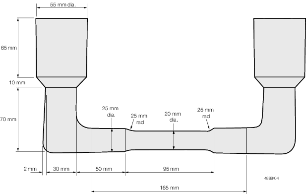
Figure 9.2.1 Sand cast test bars for long freezing range alloys
2.9.4 All welding
is to be in accordance with an approved and qualified weld procedure
and carried out by a qualified welder.
2.9.5 A statement
and/or sketch detailing the extent and position of all weld repairs
is to be prepared by the manufacturer as a permanent record. These
records are to be available for review by the Surveyor, and copies
of individual records are to be supplied to the Surveyor on request.
2.9.7 The welding
during manufacture of liners is not permitted in any alloy containing
more than 0,5 per cent lead.
2.10 Pressure testing
2.10.1 Where required
by the relevant Rules, castings are to be pressure tested before final
acceptance. Unless otherwise agreed, these tests are to be carried
out in the presence of the Surveyors and are to be to their satisfaction.
2.11 Identification
2.11.1 The manufacturer is to adopt a system of identification as per the requirements of Ch 1, 4.8 Identification of materials, which will
enable all finished castings to be traced to the original cast and the Surveyor is to be
given full facilities for tracing the castings when required.
2.11.2 Before
acceptance, all castings which have been tested and inspected with
satisfactory results are to be clearly marked by the manufacturer
with the following details:
-
Identification number,
cast number or other markings which will enable the full history of
the casting to be traced.
-
LR or Clasifications Register
and the abbreviated name of LR's local office.
-
Personal stamp of
the Surveyor responsible for inspection.
-
Test pressure, where
applicable.
-
Date of final inspection.
2.11.3 Where small
castings are manufactured in large numbers, modified arrangements
for identification may be specially agreed with the Surveyor.
2.12 Certification of materials
2.12.2 The manufacturer
is to provide the Surveyor with the following particulars for each
casting or batch of castings which has been accepted:
-
Purchaser's name and
order number.
-
Description of castings
and alloy grade.
-
Identification number.
-
Ingot or cast analysis.
-
Full details of heat
treatment, where applicable.
-
Mechanical test results.
-
Test pressure, where
applicable.
|