
Section
2 Tensile tests
2.1 Dimensions of test specimens
2.1.1 Proportional
test specimens with a gauge length L
0 of  or 5d where S
o is
the cross-sectional area, d the diameter and L
C the parallel test length, have been adopted as the standard
form of test specimen, and in subsequent Chapters in these Rules the
minimum percentage elongation values are given for test specimens
of these proportions. or 5d where S
o is
the cross-sectional area, d the diameter and L
C the parallel test length, have been adopted as the standard
form of test specimen, and in subsequent Chapters in these Rules the
minimum percentage elongation values are given for test specimens
of these proportions.
2.1.2 The gauge
length is to be greater than 20 mm and may be rounded off to the nearest
5 mm provided that the difference between the adjusted gauge length
and the calculated one is less than 10 per cent of the calculated
gauge length.
2.1.7 As an alternative
to Ch 2, 2.1 Dimensions of test specimens 2.1.6, test specimens with a
width of other than 25 mm may be used subject to any requirements
for minimum cross-sectional area given in subsequent Chapters of these
Rules. A ratio of width/thickness of 8:1 should not be exceeded.
2.1.8 For pipes
and tubes, the test specimens may consist of a suitable length tested
in full cross-section with the ends plugged. The gauge length is to
be  or 50 mm, and the length of the test specimen between
the grips or plugs, whichever is the smaller, is to be not less than
the gauge length plus D, where D is the
external diameter. Alternatively, test specimens may be prepared from
strips cut longitudinally and machined to the dimensions shown in Figure 2.2.5 Test specimen dimensions for pipes
and tubes - I or Figure 2.2.6 Test specimen dimensions for pipes
and tubes - II. The parallel test length is not to be flattened, but
the enlarged ends may be flattened for gripping in the testing machine.
The cross-sectional area of this type of test specimen is to be calculated
from: or 50 mm, and the length of the test specimen between
the grips or plugs, whichever is the smaller, is to be not less than
the gauge length plus D, where D is the
external diameter. Alternatively, test specimens may be prepared from
strips cut longitudinally and machined to the dimensions shown in Figure 2.2.5 Test specimen dimensions for pipes
and tubes - I or Figure 2.2.6 Test specimen dimensions for pipes
and tubes - II. The parallel test length is not to be flattened, but
the enlarged ends may be flattened for gripping in the testing machine.
The cross-sectional area of this type of test specimen is to be calculated
from:
where
|
S
o
|
= |
cross-sectional area |
|
a
|
= |
average
radial thickness |
|
b
|
= |
average
width |
Test specimens of circular cross-section may also be used provided
that the wall thickness is sufficient to allow the machining of such
specimens to the dimensions shown in Figure 2.2.1 Test specimen dimensions for forgings and castings - I, with their axes located at the mid-wall thickness.
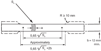
Figure 2.2.5 Test specimen dimensions for pipes
and tubes - I
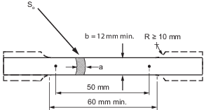
Figure 2.2.6 Test specimen dimensions for pipes
and tubes - II
2.1.9 For wire,
the test specimen may consist of a suitable length tested in full
cross-section. The gauge length is to be 200 mm and the parallel
test length 250 mm.
2.1.12 Deposited
weld metal tensile test specimens are to be machined to the dimensions
shown in Figure 2.2.9 Test specimen for deposited weld metal tensile, and may be
heated to a temperature not exceeding 250°C for a period not exceeding
16 hours for hydrogen removal, prior to testing.
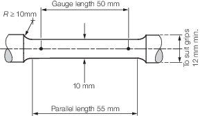
Figure 2.2.9 Test specimen for deposited weld metal tensile
2.1.13 Butt weld
tensile test specimens are to be machined to the dimensions shown
in Figure 2.2.10 Test specimen for butt weld. For thicknesses
of more than 2 mm, the test width is to be 25 mm. For thicknesses
less than 2 mm, the test width is to be reduced to 12 mm. The upper
and lower surfaces of the weld are to be filed, ground or machined
flush with the surface of the plate.

Figure 2.2.10 Test specimen for butt weld
2.1.14 Through thickness tensile test specimens may be, at the option of the
steelmaker, either plain test specimens, or test specimens with welded extensions, in
accordance with a Recognised Standard such as EN 10164 or ASTM A770/A770M.
The extension pieces are to be of steel with a tensile strength
exceeding that of the plate to be tested and may be attached to the
plate surfaces by manual, resistance or friction welding carried out
in such a way as to ensure a minimal heat affected zone.
2.1.15 Tolerances
on tensile specimen dimensions are to be in accordance with ISO 6892-1
or another Recognised Standard as appropriate.
2.2 Definition of yield stress for steel
2.2.1 The yield
phenomenon is not exhibited by all the steels detailed in these Rules
but, except for austenitic and duplex stainless steels, the term `yield
stress' is used throughout when requirements are specified for acceptance
testing at ambient temperature. For the purposes of the Rules, the
terms `yield stress' and `yield strength' are to be regarded as synonymous.
2.2.2 Where reference
is made to `yield stress' in the requirements for carbon, carbon-manganese
and alloy steel products and in the requirements for the approval
of welding consumables, either the upper yield stress or, where this
is not clearly exhibited, the 0,2 per cent proof stress or the 0,5
per cent proof stress under load is to be determined. In cases of
dispute, the 0,2 per cent proof stress is to be determined.
2.2.3 For austenitic
and duplex stainless steel products and welding consumables, both
the 0,2 and the 1,0 per cent proof stresses are to be determined.
2.3 Procedure for testing at ambient temperature
2.3.1 Except as provided in Ch 2, 2.3 Procedure for testing at ambient temperature 2.3.5, the elastic stress rate for the determination of
the upper yield for steels is to be between 6 and 60 N/mm2 per second and
between 2 and 20 N/mm2 per second for aluminium and copper alloys. After
reaching the yield or proof load, the straining rate may be increased to a maximum of
0,008s
–1 for the determination of the tensile strength.
2.3.2 For steel,
the upper yield stress is to be calculated from:
-
the value of stress
measured at the commencement of plastic deformation, or
-
on a load/extension
diagram using the value of stress measured at the first peak obtained
during yielding even when the peak is equal to or less than any subsequent
peaks observed during plastic deformation at yield.
2.3.3 When a well
defined yield point cannot be obtained, the 0,2 or 1,0 per cent proof
stress (non-proportional elongation) is to be determined from an accurate
load/extension diagram by drawing a line parallel to the straight
elastic portion and a distance from it where the amount represents
0,2 or 1,0 per cent of the extensometer gauge length. The point of
intersection of this line with the plastic portion of the diagram
represents the proof load, from which the 0,2 or 1,0 per cent proof
stress can be calculated.
2.3.4 For stainless
steels the 1,0 per cent proof stress and/or 0,2 per cent proof stress
is specified as required by the relevant Chapters in these Rules.
2.3.5 For the determination of the tensile strength of flake graphite cast iron,
the strain rate is not to exceed 0,0067 per second.
2.4 Equivalent elongations
2.4.1 When a gauge
length other than  is used, the equivalent percentage elongation value is
to be calculated using the following formula: is used, the equivalent percentage elongation value is
to be calculated using the following formula:
where
|
A
R
|
= |
actual measured percentage elongation of test specimen |
|
S
o
|
= |
actual cross-sectional area of test specimen |
|
L
o
|
= |
actual gauge length of test piece |
|
A
|
= |
equivalent
percentage elongation for a test specimen with a gauge length of 
|
2.4.2 Alternatively,
where a number of test specimens of similar material and dimensions
are involved, the actual percentage elongation values may be recorded,
provided that the equivalent specified minimum elongation value appropriate
for the test specimen dimensions is calculated from the formula in Ch 2, 2.4 Equivalent elongations 2.4.1 and is recorded on the test certificate.
2.4.4 For non-proportional test specimens with gauge lengths of 50 mm and 200 mm,
the equivalent elongation values tabulated in ISO 2566-1 are to apply. For Austenitic
steels, conversion of room temperature percentage elongations after fracture obtained on
various proportional and non-proportional gauge lengths to other gauge lengths shall be
in accordance with ISO 2566-2.
2.4.5 The above
conversions are reliable only for carbon, carbon-manganese and low
alloy steels with a tensile strength not exceeding 700 N/mm2 in
the hot rolled, annealed, normalised, or normalised and tempered condition.
2.4.7 Any proposals
to use conversion factors for equivalent elongation values for the
following materials are to be agreed with the Surveyors:
-
Carbon, carbon-manganese
and alloy steels in the normalised or normalised and tempered condition
with a tensile strength exceeding 700 N/mm2.
-
Cold-worked steels.
-
Austenitic stainless
steels.
-
Non-ferrous alloys.
2.5 Procedure for testing at elevated temperatures
2.5.1 Tensile testing
at elevated temperatures is to be carried out according to ISO 6892-2
Method B or an equivalent National Standard.
|