
Section
1 Introduction
1.1 Background
1.1.1 This guidance note has been produced to provide guidance on the Classification of
tugs with Lloyd’s Register, including information on tug types, operational
restrictions, notations and design calculations. In addition, for tugs with a
(freeboard) length LLL ( as defined in the International Convention on
Load Lines (ICLL)) of not more than 100 m, this note goes beyond the limited scope
of Class Rules to provide guidance on best practice and general statutory
requirements.
1.2 Scope
1.2.1 The content of this guidance note relating to Classification aspects is
relevant to all tugs eligible for Classification to which one or more of the Type
Notations specified in Ch 2, 1.1 Type and Service Restriction Notations intended
to be are assigned.
1.2.2 The content of this guidance note relating to statutory aspects is relevant to tugs
having a (freeboard) length LLL, as defined in the International
Convention on Load Lines (ICLL), of not more than 100 m.
1.2.3 Classification of tugs requires that the vessel complies with the Rules
and Regulations of Lloyds Register. The relevant requirements are made up of the
general requirements for all vessels in the Rules and Regulations for the
Classification of Ships (The Rules and Regulations for the Classification of Ships, July 2022) and any relevant specific
requirements.
For all tugs the Classification requirements may include;
- Pt 1, Ch 2, 2.1 Definitions 2.1.6
- Pt 1, Ch 2, 3.2 New construction surveys 3.2.6
- Pt 3, Ch 1, 7.1 Calculation of Equipment Number 7.1.6
- Pt 3, Ch 8, 5.5 Special requirements for tugs and offshore supply ships
- Pt 3, Ch 13, 7 Equipment
- Pt 4, Ch 3 Tugs
The above list of applicable requirements is not exhaustive and may vary from vessel
to vessel based on the operational profile, the tug type, equipment, fit out
etc.
1.2.4 All vessels are subject to the requirements set out by their relevant Flag
Administration(s). Typically, such statutory requirements go beyond the scope of
class. This Guidance note sets out some general guidelines in these areas however in
all cases the requirements of the relevant flag Administration(s) are to be
applied.
1.2.5 There should be no instances where this guidance conflicts with the requirements of
the Flag Administration, however if an instance is identified for a vessel that is
to be Classed the conflict should be highlighted to Lloyd’s Register at the earliest
opportunity to ensure that the conflict is rectified as soon as possible to allow
Classing and Flagging of the vessel.
1.2.6 The Rules and these guidance notes assume that no escort operations will be conducted
at speeds greater than 10 kn, however for vessels designed to conduct escort at
speeds greater than this application of the Rules and these guidance will be
specially considered.
1.2.7 The sizing of the prime mover and the propulsion chain to develop sufficient thrust
for the vessel to perform her predicted duties is beyond the scope of
Classification.
1.3 Definitions
1.3.1 Design bollard pull
The design bollard pull TBP, in kN, is the maximum sustained
towline force a tug is capable of generating at zero forward speed, to be initially
specified by the designer and to be verified by a full scale test, generally
referred to as bollard pull test.
Where TBP is not available, the following default values may be
used as an estimate for a preliminary design review:
-
|
TBP |
= |
0,204NPS for conventional tugs with propellers
fitted with nozzles; |
-
|
TBP |
= |
0,176NPS for tractor tugs and ASD tugs with
steerable propellers fitted with nozzles |
where:
N : number of propellers;
PS : maximum continuous power per propeller shaft, in kW.
1.3.2 Escort forces and speed
The steady towline force during escorting, Ft in kN, is the towline
force associated with the (quasi-static) equilibrium in indirect towing mode,
excluding short time-duration dynamic effects, for a given loading condition and
escort speed V, see
Figure 1.1.1 Typical escort configuration. The
steady towline force is applied by the tug on the stern of the escorted ship.
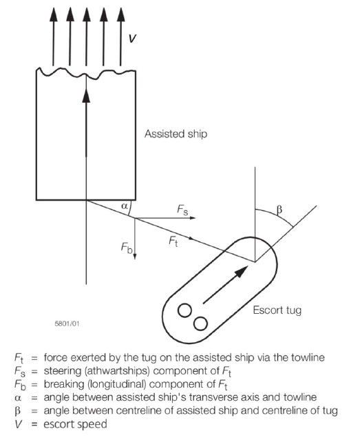
Figure 1.1.1 Typical escort configuration
Additionally, the steady towline force Ft can be decomposed into a
steering force Fs and a braking force Fb :
- The steering force Fs, in kN, is the transverse component
of the steady towline force Ft with respect to the
escorted ship;
- The braking force Fb, in kN, is the longitudinal component
of the steady towline force Ft with respect to the
escorted ship.
For the purpose of this guidance note the following rated values of the above defined
escort forces are defined as:
- The rated steady towline force Ft,R, in kN, is the highest
anticipated steady towline force Ft, as obtained from the
evaluation of the escort forces for a particular loading condition and
escort speed, taking into account the applicable stability and strength
criteria in this guidance note;
- The rated steering force Fs,R, in kN, is the highest
anticipated steering force Fs, as obtained from the
evaluation of the escort forces for a particular loading condition and
escort speed, taking into account the applicable stability and strength
criteria in this guidance note;
- The rated maximum braking force Fb,R, in kN, is the
highest anticipated braking force Fb, as obtained from the
evaluation of the escort forces for a particular loading condition and
escort speed, taking into account the applicable stability and strength
criteria in this guidance note.
And the associated maximums are,
- The design maximum steady towline force Ft,MAX, in kN, is
the highest rated steady towline force Ft,R over the
applicable range of loading conditions and escort speeds;
- The design maximum steering force Fs,MAX, in kN, is the
highest rated steering force Fs,R over the applicable
range of loading conditions and escort speeds;
- The design maximum braking force Fb,MAX, in kN, is the
highest rated braking force Fb,R over the applicable range
of loading conditions and escort speeds.
- The maximum escort speed VMAX, in kn, is the highest
escort speed V for which the escort tug is considered to perform
escort operations.
For the purpose of this guidance note the following relevant angles are defined
as:
- The towline angle α, in deg, is the angle between the towline and the
centreline of the escorted ship and;
- The drift angle β, in deg, is the angle between the centreline of the tug
and the centreline of the escorted ship (also referred to as yaw
angle).
1.3.3 Reference towline force
The reference (quasi-static) towline force T, in kN, is considered
to represent:
1.3.4 Design load
The design load (DL), in kN, is the force taken into consideration for the strength
assessment and testing of the towing equipment and the associated supporting
structures, and for the purposes of design appraisal it is taken as not less than:
where
DAF: dynamic amplification factor
The dynamic amplification factor takes into consideration dynamic effects. Reference
values for the dynamic amplification factor are given in:
1.3.5 Winch brake holding load
The winch brake holding load (BHL), in kN, is the maximum towline force the towing
winch can withstand without slipping of the (activated) brake, considering the
towline at the first inner layer.
The BHL is a reference value for strength assessment and testing of towing winches
and associated towing fittings (e.g. fairlead, staple, gob-eye) as well as their
supporting structures.
1.3.6 Towline breaking strength
The towline breaking strength, in kN, is the tension required to cause failure of the
towline (parting of the towline).
1.4 General Guidance
1.4.1 All bollard pull tests should be performed in accordance with a recognised Standard,
such as the ‘Lloyd’s Register Bollard Pull certification procedures guidance
information’, and witnessed by a Lloyd’s Register Surveyor.
1.4.2 For tugs capable of towing over the stern (ahead towing) as well as over the bow
(astern towing), the bollard pull test should be performed for both scenarios.
1.4.3 If the measured bollard pull for any vessel is higher than the design bollard pull
(TBP) by 1 per cent or more then aspects of the design
appraisal of the vessel may need to be redone reflecting this new bollard pull. The
extent of reappraisal is at the discretion of Lloyds Register.
1.4.5 The matrix of rated steady towline forces Ft,R, steering forces
Fs,R and braking forces Fb,R should be
specified by the designer for design appraisal and are latterly verified by Lloyd’s
Register on the basis of the results of:
- full scale trials, or
- model testing, or
- a computer simulation program accepted by Lloyd’s Register.
1.4.6 All full scale trials conducted to verify the above matrix of forces,
should be performed in accordance with a procedure agreed with Lloyd’s Register
prior to commencement of the trials. Further guidance on such trials is contained in
Ch 3, 2.3 Intact stability 2.3.6.
1.4.7 All Model testing, where applicable, should be performed in accordance
with a procedure agreed with Lloyd’s Register before commencement of the tests. The
testing should comply with the relevant aspects of Ch 3, 2.3 Intact stability 2.3.6.
1.4.8 Special attention should be paid to scale effects when processing any model scale
measurement results to create predictions at full scale.
1.4.11 In order to maintain the Classification of any tug, the vessel will be
subject to an ongoing periodical survey regime to ensure that the vessel and the
equipment relevant for Classification remain in a worthy condition. Details of the
through life survey requirements can be found in Part 1 of the Rules and Regulations for the Classification of Ships, July 2022.
1.4.12 For high powered escort tugs (with a free running speed of more than 15 kn) Lloyd’s
Register will specially consider the application of the Rules and these Guidance
notes to the vessel assuming an escort speed of 12 kn.
1.4.13 Propulsion engines and propulsion train should develop sufficient thrust for
manoeuvring the tug quickly for any drift angle, and in the case of loss of
propulsion, the heeling moment due to the remaining forces should lead to a safe
equilibrium position of the tug with reduced heeling angle.
1.5 Escorting dynamics
1.5.1 For the purpose of this guidance note, escorting is considered to include active
(emergency) steering, braking and otherwise controlling of the escorted ship by the
tug operating in indirect towing mode, whereby the ahead speed of the escorted ship
is within a typical speed range of 6 to 10 kn.
1.5.2 In indirect towing mode the towline force is the resultant of the (quasi-static)
equilibrium condition reached between the forces and moments arising from the
hydrodynamic lift and drag forces acting on the hull and appendices of the tug
advancing through the water at a drift angle relative to the water flow, the thrust
vector and the towline force (In direct towing mode the thrust is directly applied
to generate the towline force, hydrodynamic lift and drag forces play no significant
role).
Escort tugs may work in different indirect towing modes, depending on the required
action towards the escorted ship (e.g. steering, braking). The main indirect towing
modes relevant for escort tugs are schematically shown in Figure 1.1.2 Schematic overview of indirect towing modes (escort tug). Where reference is made to ‘indirect steering’ the
objective is to maximise the steering force in indirect towing mode. Where reference
is made to ‘indirect braking’ the objective is to maximise the braking force in
indirect towing mode.
In (basic) indirect mode the towline force is generated primarily by the hydrodynamic
forces acting on the hull and skeg, with the thrust used solely to maintain the
desired drift angle (also referred to as yaw angle).
In powered indirect mode (indirect steering) the transverse component of thrust is
used to maintain the desired drift angle, while a significant longitudinal component
of thrust is applied in forward direction of the tug.
Compared to the (basic) indirect mode, the tug is operating more sideways of the
escorted ship with a relatively large towline angle, generating a higher steering
force.
In combination mode (indirect braking) the same principle as for the indirect
steering mode is applied, except that the longitudinal component of thrust is
applied in aftward rather than forward direction.
Compared to the (basic) indirect mode, the tug is operating more behind the escorted
ship with a relatively small towline angle, generating a higher braking force.
For indirect towing modes it is generally recognised that it is beneficial to design
the tug to generate high (indirect) towline forces with minimal propulsion thrust,
while respecting the limits imposed by stability and strength considerations (towing
equipment, general hull structure).
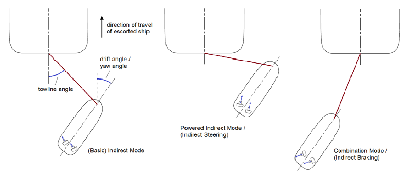
Figure 1.1.2 Schematic overview of indirect towing modes (escort tug)
|