
Section
2 Stability
2.1 Scope of application
In general, tugs having a Load Line length LLL equal to or greater than
24 m may be assigned class only after it has been demonstrated that their intact
stability is adequate. Adequate intact stability means compliance with standards laid
down by the relevant Administration.
The content of this Section may also be applied to tugs with a Load Line length
LLL of less than 24 m in length as desired.
2.2 Openings
2.2.1 General
Openings in the hull, superstructures or deckhouses which cannot be closed
weathertight should be considered as unprotected openings and, consequently, as
down-flooding points for the purpose of stability calculations (the lower edge of
such openings should to be taken into account).
2.2.2 Ventilation openings of machinery space and emergency generator room
It is recognised that for tugs, due to their size and arrangement, compliance with
the requirements of ICLL Reg. 17(3) for ventilators necessary to continuously supply
the machinery space and the emergency generator room may not be practicable. Lesser
heights of the coamings of these particular openings may be accepted by the
administration if the openings:
- are positioned as close to the centreline and as high above the deck as
practicable in order to maximise the downflooding angle and to minimise
exposure to green water;
- are provided with weathertight closing appliances in combination with
suitable arrangements, such as separators fitted with drains;
- are equipped with efficient protective louvers and mist eliminators;
- have a coaming height of not less than 900 mm above the deck;
- are considered as unprotected openings and, consequently, as down-flooding
points for the purpose of stability calculations.
2.3 Intact stability
2.3.1 Loading conditions
The following standard loading conditions should be included in the
stability booklet:
- lightship condition;
- tug in lightest anticipated loading condition, with full stores
and fuel;
- same condition as above, but with 10 per cent stores, provisions
and consumables;
- tug in the departure condition at the waterline corresponding to
the maximum draught, with full stores, provisions and consumables;
- same condition as above, but with 10 per cent stores,
provisions and consumables.
For the lightship condition, not being an operational loading condition,
the administration may accept that part of the mentioned criteria is not
fulfilled.
In case a tug is fitted with water ballast tanks the lightest anticipated
loading condition may be a ballast condition (in particular for larger tugs).
When a tropical freeboard is to be assigned to the tug, the corresponding
loading conditions should also be included.
For the loading condition corresponding to the maximum draught, when
necessary, deck cargo may be applied to arrive at the required draught. Attention
should be paid to the associated wind profile for verification of the severe wind
and rolling criterion, refer to part A, 2.3 of the International Code on Intact
Stability, 2008.
Additional loading conditions that should be included in the stability
booklet:
- tug in the worst anticipated operating conditions for towing,
covering the relevant range of draughts, for type notation tug;
- tug in the worst anticipated operating conditions for escorting,
covering the relevant range of draughts, for type notation escort
tug.
Further loading conditions may be included when deemed necessary or
useful by the administration.
2.3.2 Stability criteria
The intact stability of tugs should comply with the provisions given in
part A, 2.2 and 2.3 of the International Code on Intact Stability, 2008, except that
the alternative criteria given in part B, 2.4.5, which apply to offshore supply
vessels, may be used for tugs of similar design and characteristics.
With reference to Part B, 5.1.4 of the International Code on Intact
Stability, 2008, tugs should possess an adequate reserve of stability to withstand
the anticipated heeling moment arising from the towline. It is considered that this
requirement is complied with in case a tug meets the additional stability criteria
as specified in Ch 3, 2.3 Intact stability 2.3.3 and/or Ch 3, 2.3 Intact stability 2.3.4, as applicable.
2.3.3 Additional stability criteria for type notation tug
All the loading conditions reported in the trim and stability booklet
which are intended for towing operations should also be checked in order to
investigate the tug’s capability to withstand the effect of the transverse heeling
moment induced by the combined action of the towline force and the thrust vector
(self-tripping), and induced by the hydrodynamic resistance of the hull
(tow-tripping).
The stability calculations should to be performed on the basis of the
design bollard pull, as defined in Ch 1, 1.3 Definitions 1.3.1.
For tugs capable of towing over the stern as well as over the bow, this
check should be performed for both towing situations, duly taking into account the
location of the associated towing points. If different values of the ahead and
astern design bollard pull are available, it may be acceptable to consider the ahead
bollard pull for towing over the stern and the astern bollard pull for towing over
the bow.
The values of the ahead and astern design bollard pull, as applicable,
should be specified by the designer in the stability booklet. In addition, an
arrangement drawing with the location of the towing point(s) and propulsion unit(s)
should be included in the stability booklet. In this drawing the longitudinal and
vertical distance, in m, from each of the towing points to the relevant centrelines
of the propulsion unit(s) and the baseline, respectively, should be clearly
specified.
Preliminary stability calculations on the basis of estimated bollard
pull values may be submitted for (preliminary) examination. If after completion of
the bollard pull test the measured bollard pull values exceed the estimated values,
the stability calculations should be updated for the measured bollard pull values.
It is recommended to include a reasonable margin in the estimated values (on the
basis of design experience).
A tug may be considered as having sufficient stability to
withstand the self-tripping heeling moment if the following condition is satisfied
with ( see
Figure 3.2.1 Heeling and righting arm curves):
where
|
A |
= |
Area, in m rad, contained between the righting arm and the
heeling arm curves, measured from the heeling angle θC to the
heeling angle θD; |
|
B |
= |
Area, in m rad, contained between the heeling arm and the
righting arm curves, measured from zero heel (θ = 0) to the heeling
angle θC; |
|
θC |
= |
Heeling angle of equilibrium, corresponding to the first
intersection between heeling and righting arm curves; |
|
θD |
= |
Heeling angle, to be taken as the lesser of:
- heeling angle corresponding to the second
intersection between heeling and righting arms heeling and
righting arm curves;
- angle of down-flooding.
|

Figure 3.2.1 Heeling and righting arm curves
The self-tripping heeling arm curve should be calculated as
follows:
where
|
bHi |
= |
Heeling arm induced by one thruster or group of thrusters i, in
m, calculated as follows:
|
|
TBPi |
= |
Amount of thrust, in kN, generated by one thruster or group of
thrusters i. The sum of all the individual thrusts is to be equal to the
design bollard pull, as defined in Ch 1, 1.3 Definitions 1.3.1; |
where
|
hi |
= |
Vertical distance, in m, between the towing point (fairlead,
staple, towing hook or equivalent fitting) and the horizontal centreline of
the propulsion unit or group of units i, as relevant for the considered
towing situation; |
|
r |
= |
Transverse distance, in m, between the centreline and the
towing point (fairlead, staple, towing hook or equivalent fitting), to be
taken equal to zero when the towing point is fixed at the vessel’s
centreline; |
|
ci |
= |
Coefficient to be taken equal to:
ci = 0,50
for tugs with non-azimuth propulsion unit or group of units
(conventional tug, see
Ch 1, 2.2 Typical tug arrangements 2.2.2);
ci = 1/(1 + d
i/LLL) for a single azimuthing
thruster
ci = 0,90/(1 + d
i/ LLL) for tugs with a group of two azimuthing
thrusters (tractor tug and ASD tug, see
Ch 1, 2.2 Typical tug arrangements 2.2.3 and Ch 1, 2.2 Typical tug arrangements 2.2.4, respectively, as well as similar tug designs), as
relevant for the considered towing situation, but is in no case to be
taken as less than:
- 0,70 for ASD tugs towing over the stern and tractor
tugs towing over the bow
- 0,50 for ASD tugs towing over the bow and tractor
tugs towing over the stern, respectively;
|
|
Δ |
= |
Loading condition displacement, in t; |
|
ϴ |
= |
Angle of heel, in deg; |
|
di |
= |
Longitudinal distance, in m, between the towing point
(fairlead, staple, towing hook or equivalent fitting) and the vertical
centreline of the propulsion unit or group of units i, as relevant for the
considered towing situation; |
|
LLL |
= |
Load Line length, in m. |
A tug may be considered as having sufficient stability to
withstand the tow-tripping heeling moment if the first intersection between the
righting arm curve and the tow-tripping heeling arm curve occurs at an angle of heel
less than the angle of down-flooding.
The tow-tripping heeling arm curve is to be calculated as
follows:
where
|
Ci |
= |
Lateral traction coefficient, taken equal to:
without being taken lower than 0,1 and
greater than 1;
|
|
Ls |
= |
Longitudinal distance, in m, from the aft perpendicular to the towing
point; |
|
Lpp |
= |
Length between perpendiculars, in m; |
|
C2 |
= |
Angle of heel correction for C1, taken equal to:
without being taken lower than 1;
|
|
ϴd |
= |
Angle to deck edge, in deg, taken equal to:
|
|
f |
= |
Freeboard amidships, in m; |
|
γ |
= |
Specific water density, in t/m3, to be taken equal to 1,025; |
|
V |
= |
Lateral velocity, in m/s, to be taken equal to 2,57 (5 kn); |
|
Ap |
= |
Lateral projected area, in m2, of the underwater hull; |
|
C3 |
= |
Distance from the centre of Ap to the waterline as a
fraction of the draught related to the heeling angle, taken equal
to:
without being taken lower than 0,5 and greater than
0,83;
|
|
T |
= |
Loading condition draught, in m. |
2.3.4 Additional stability criteria for type notation escort tug
All the loading conditions reported in the trim and stability booklet which are
intended for escorting operations should also be checked in order to investigate the
tug’s capability to withstand the effect of the transverse heeling moment induced by
the combined action of the following forces:
- hydrodynamic forces acting on the hull and appendices;
- thrust forces;
- steady towline force.
The stability calculations should to be performed on the basis of the
highest anticipated heeling moment for the considered loading condition, which
should to be obtained from the results of full scale tests, model tests, or,
alternatively; the results of an accepted computer simulation program (refer to
Ch 3, 2.3 Intact stability 2.3.5).
For each relevant loading condition the evaluation of the highest
anticipated heeling moment should be performed for the applicable range of speeds
and towline angles, as defined in the escort towing arrangement plan (see
Ch 2, 2.3 Towing arrangements for Escort Tugs 2.3.4). As a minimum, the conditions corresponding to the design maximum
steering force Fs,MAX, and design maximum braking force
Fb,MAX, as defined in Ch 1, 1.3 Definitions 1.3.2, should be
included in the evaluation.
The highest anticipated heeling moment should be assumed constant for the purpose of
the stability calculations.
The value of the highest anticipated heeling moment should be specified by the
designer in the stability calculations. In addition, an arrangement drawing with the
location of the towing points and propulsion units should be included in the
stability booklet. In this drawing the longitudinal and vertical distance, in m,
from the towing point to the relevant centrelines of the propulsion units and the
baseline, respectively, should be clearly specified.
Preliminary stability calculations on the basis of estimated highest
heeling moment and associated heeling arm values may be submitted for (preliminary)
examination. If after verification of the heeling arm values on the basis of the
results of escort performance trials, model tests or an accepted computer simulation
program (refer to Ch 3, 2.3 Intact stability 2.3.5) the final values exceed
the estimated values, the stability calculations should be updated for the final
heeling moment and heeling arm values. It is recommended to include a reasonable
margin in the estimated values (on the basis of design experience).
An escort tug may be considered as having sufficient stability to
withstand the heeling moment arising from the towline, if the three following
conditions are satisfied with:
where
|
A |
= |
Righting arm curve area, in m rad, measured from the heeling
angle θC to a heeling angle of 20 deg (see
Figure 3.2.2 Definition of areas A and B); |
|
B |
= |
Heeling arm curve area, in m rad, measured from the heeling
angle θC to a heeling angle 20 deg (see
Figure 3.2.2 Definition of areas A and B); |
|
C |
= |
Righting arm curve area, in m rad, measured from the zero
heel (θ = 0) to the heeling angle θD (see
Figure 3.2.3 Definition of areas C and D); |
|
D |
= |
Heeling arm curve area, in m rad, measured from zero heel (θ
= 0) to the heeling angle θD (see
Figure 3.2.3 Definition of areas C and D); |
|
θC |
= |
Heeling angle of equilibrium corresponding to the first
intersection between heeling arm and righting arm curve, to be obtained
when the highest anticipated heeling moment resulting from the steady
towline force Ft as defined in Ch 1, 1.3 Definitions 1.3.2, is
applied to the escort tug; |
|
θD |
= |
Heeling angle, to be taken as the lesser of:
- the angle of down-flooding;
- 40 deg;
- the heeling angle corresponding to the second
intersection between heeling and righting arms heeling and
righting arm curves.
|
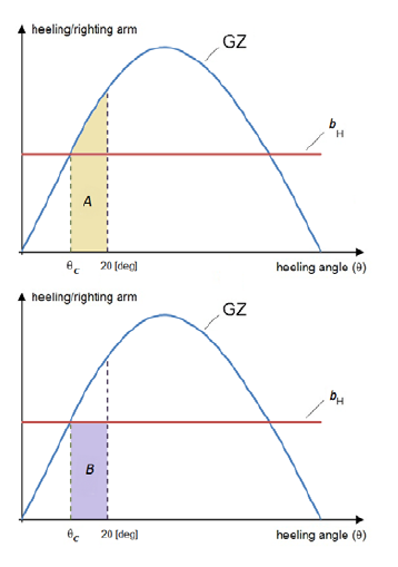
Figure 3.2.2 Definition of areas A and B
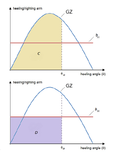
Figure 3.2.3 Definition of areas C and D
2.3.5 Escort performance simulations
Where the highest anticipated heeling moment is obtained from the results of a
computer simulation program, the basic assumptions and theoretical models underlying
the software should be presented in detail to Lloyd’s Register. Items to be detailed
include:
- hydrodynamic lift and drag computation (hull and appendices);
- modelling of thrust forces;
- interaction effects between hull, skeg and (steerable) propulsion
units;
- flow separation effects;
- water pile-up effects;
- effects of waves and/or swell;
- dynamic effects before a steady state is reached (e.g. during initiation and
turning manoeuvres) and scaling effects (if any).
- Meshing details
- Model assumptions and relevant limitations
A validation report, containing comparisons between simulation results and full scale
and/or model test results, should also be presented.
A clear description of the input and output data should be provided, along with
explanations on how the output data are obtained/calculated by the software.
As a minimum, for each relevant loading condition ( see
Ch 3, 2.3 Intact stability 2.3.1) the following set of
results should be provided in tabular form as function of the escort speed for the
rated values of the steering force Fs,R and the braking force
Fb,R:
- Rated steering force Fs,R or steering force
Fs corresponding to rated braking force
Fb,R, as applicable;
- Rated braking force Fb,R or braking force
Fb corresponding to rated steering force
Fs,R, as applicable;
- Corresponding towline force Ft;
- All corresponding forces acting in transverse direction
(hydrodynamic, thrust and towline);
- Corresponding heeling angle;
- Corresponding heeling moment;
- Corresponding towline angle relative to the escorted ship
(see α in Figure 1.1.1 Typical escort configuration);
- Corresponding drift angle of the escort tug (see β in
Figure 1.1.1 Typical escort configuration).
Note that the highest anticipated values of the steering force, braking force,
towline force and heeling moment do not normally all occur in the same condition
(defined by the position of escort tug relative to the escorted ship and the drift
angle), although more than one parameter may have its highest value in a particular
condition. Hence it is suggested to consider at least two conditions: one for the
highest anticipated steering force and one for the highest anticipated braking
force. In case the highest anticipated heeling moment and/or towline force do not
occur in either one of these two conditions, the relevant conditions should be
added.
It is recommended that the results of the escort performance simulations are
presented in the form of diagrams showing the envelope of the (steady state)
combinations of steering and braking forces obtained from the simulations. Such
diagrams should cover the applicable escort speed range, with a recommended step of
2 knots.
2.3.6 Escort performance trials
Escort performance trials at full scale or model scale may be carried out in order to
obtain the characteristics of escort tugs.
The trials should cover the applicable range of loading conditions and escort
speeds.
The following documents should be submitted for information prior to testing:
- Relevant loading conditions, defined by draught (or displacement) and trim,
for which the tug is designed to perform escort services;
- Applicable range of test speeds of the escorted ship: the speed is defined
as the relative speed with respect to the sea, taking into account current
effects;
- Main propulsion characteristics, in particular power and maximum orientation
angle of the rudder(s) (propellers);
- Preliminary calculation of the rated steering force
Fs,R, rated braking force Fb,R and
rated steady towline force Ft,R as defined in Ch 1, 1.3 Definitions 1.3.2, as well as the
corresponding heeling moments and heeling angles, for the range of test
speeds;
- Calculation of the route deviation of the escorted ship (for testing
purposes the escorted ship is to be selected so that the route deviation
induced by the tug is kept reasonably small;
- Preliminary stability calculations for the above-mentioned conditions;
- Escort towing arrangement plan, including the load cell and specification of
the components;
- Documentation relevant to the Bollard Pull test, see
Ch 1, 1.3 Definitions 1.3.1.
Prior to commencing the escort performance trials the following data should be
recorded:
- Wind speed and direction;
- Sea state, including significant wave height and peak period;
- Current speed and direction;
- Water depth;
- Loading condition of the escort tug: draught (or displacement) and
trim;
- Loading condition of the escorted ship.
Testing should be performed over the applicable range of towline angles as defined in
the escort towing arrangement plan. The length of the towline and the angle of the
towline with the horizontal plane should represent a typical operating
condition.
As a minimum, the following data should be collected during testing for
post-processing and analysis:
It is also recommended to that the following data is measured:
- Power setting and orientation angle of rudder(s) (propellers) of the escort
tug;
- Time needed to swing the tug from the equilibrium position to its mirror
position.
For each combination of loading condition and test speed:
- The rated steering force Fs,R and rated braking force
Fb,R should be calculated on the basis of the
corresponding measured steady towline force Ft and the
associated measured towline angle, drift angle and the angle between the
towline and the horizontal plane;
- The maximum heeling arm should be calculated on the basis of
the corresponding measured steady towline force Ft, as
defined in Ch 1, 1.3 Definitions 1.3.2, the associated
measured heeling angle and the GZ curve applicable to the loading condition
considered (The GZ curve should be based on the escort tug in upright
position before commencing the escort operation).
As a minimum, for each tested loading condition the following set of results should
be provided in tabular form as a function of the escort speed for the rated values
of the steering force Fs,R and the braking force
Fb,R:
- Rated steering force Fs,R or steering force
Fs corresponding to rated braking force
Fb,R, as applicable;
- Rated braking force Fb,R or braking force
Fb corresponding to rated steering force
Fs,R, as applicable;
- Corresponding towline force Ft,R;
- Corresponding heeling angle;
- Corresponding heeling moment;
- Corresponding towline angle relative to the escorted ship (see α in
Figure 1.1.1 Typical escort configuration);
- Corresponding drift angle of the escort tug (see β in Figure 1.1.1 Typical escort configuration).
The highest anticipated values of the steering force, braking force, towline force
and heeling moment do not normally all occur in the same condition (defined by the
position of escort tug relative to the escorted ship and the drift angle), although
more than one parameter may have its highest value in a particular condition. Hence
it is suggested to consider at least two conditions: one for the highest anticipated
steering force and one for the highest anticipated braking force. In case the
highest anticipated heeling moment and/or towline force do not occur in either one
of these two conditions, the relevant conditions should be added.
For model testing, due consideration should be given to scale effects for
establishing the escort tug characteristics at full scale from the model test
results.
2.3.7 Operating information for type notation escort tug
Additional operating information should be provided in the stability
booklet in relation to the design limitations related to the assignment of the type
notation escort tug, in line with Pt B, Ch 3.8 of the International Code
on Intact Stability, 2008.
As a minimum, the following information should be included:
- Design service restriction notation and environmental conditions for
performing escort operations;
- The maximum escort speed VMAX (see
Ch 1, 1.3 Definitions 1.3.2);
- A table with permissible values of heeling angle and steady
towline force as function of loading condition and escort speed (based on
the rated steering and braking forces as obtained from Ch 3, 2.3 Intact stability 2.3.5 orCh 3, 2.3 Intact stability 2.3.6, as applicable);
- Instructions to the master regarding the handling of the escort tug and the
associated towing equipment, demonstrating the implementation of effective
means to limiting the steady towline force and heeling angle within the
permissible limits and the use of the emergency quick-release device. In
this context “Effective means” might include, but is not limited to,
adjustable audible or visible alarms, providing a warning to the master when
the heeling angle and/or steady towline force exceeds the permissible
value(s) applicable to the relevant loading condition and escort speed.
The table with permissible values of heeling angle and steady towline force as
function of loading condition and escort speed should be displayed in the wheelhouse
next to the control desk or another appropriate location.
2.3.8 Icing considerations
For tugs operating in areas where ice accretion is expected due consideration should
be given to the stability affecting effect of added weight due to ice accretion.
To this end, relevant loading conditions, including ice accretion should
be included in the stability booklet, together with detailed calculations of the
expected ice accretion a required by Pt B, Ch 6 of the International Code on
Intact Stability, 2008.
2.3.9 Elements reducing stability
Provisions should be made for a safe margin of stability at all stages of the voyage,
due regard being given to additions of weight, such as those due to absorption of
water and icing and to losses of weight such as those due to consumption of fuel and
stores.
2.3.10 Alterations
Where any alterations are made to a tug or its towing equipment so as to materially
affect the stability information supplied to the master, amended stability
information should be provided.
During the lifetime of the vessel, it is recommended that periodical lightweight
surveys are undertaken to verify any changes in lightship displacement and
longitudinal centre of gravity. In the case that case significant deviations are
found in comparison with the approved stability information, it may be necessary to
(re-)incline the tug and/ or reassess the strength and stability of the vessel.
|