
Section
2 Classification Guidance
2.1 Hull
2.1.1 The Hull design and construction requirements for tugs are all contained
within the Rules and Regulations for the Classification of Ships, July 2022 and both vessels with the
Type notation Tug or Escort Tug are to comply with the Rules and
regulations of this Ruleset to be eligible for classification with Lloyds
Register.
In addition to the Ship structures (general) requirements for all vessels
of the Rules and Regulations for the Classification of Ships, July 2022 (all contained within Pt 3), there are is
also a specific ship structures section of the Rules dedicated to tug structures.
This section is Pt 4, Ch 3 Tugs and it contains the following
sections:
- Pt 4, Ch 3, 1 General
- Pt 4, Ch 3, 2 Longitudinal strength
- Pt 4, Ch 3, 3 Floors in single bottoms
- Pt 4, Ch 3, 4 Panting and strengthening of bottom forward
- Pt 4, Ch 3, 5 Machinery casings
- Pt 4, Ch 3, 6 Freeing arrangements
- Pt 4, Ch 3, 7 Towing arrangements
- Pt 4, Ch 3, 8 Fenders
- Pt 4, Ch 3, 9 Escort operation, performance numeral and trials
The content of each of these sections is generally self-explanatory with
content referring out to other sections of the Rules and Regulations for the Classification of Ships, July 2022 to be complied with and/or listing
additional requirements or exceptions.
Of particular interest in the above is Pt 4, Ch 3, 7 Towing arrangements and Pt 4, Ch 3, 8 Fenders (additionally Pt 4, Ch 3, 9 Escort operation, performance numeral and trials for Escort Tugs), these are discussed in the following
sub-Sections.
2.2 Towing arrangements for Tugs
2.2.1 The Rule requirements relating to the towing equipment and their
foundations are contained within Pt 4, Ch 3, 7 Towing arrangements of The Rules and Regulations for the Classification of Ships, July 2022.
In addition, materials used in towing equipment should comply with the applicable
class requirements for materials. Class certificates are generally required for the
materials used for winch drums, drum shafts, winch brake components, winch
supporting frames, towing hooks and towline guiding fittings installed upon classed
vessels.
2.2.2 Documents to be submitted
In order for the plan appraisal of the towing equipment and the associated
foundations to be undertaken, the following documents should be submitted for
appraisal (assuming no Type Approval is in place):
- Drawings of towing winches, including winch drums, main shaft, load carrying
non-rotating structures (support frame), winch brakes. Gear and clutch
information is also to be submitted for information;
- Hydraulic, electrical and control system diagrams of the towing winch, as
applicable (note that this may be used for information as required);
- Drawings of towing hook and towline guiding fittings;
- Drawings of foundations and under deck supporting structures (clearly
showing reinforcements) of towing equipment including scantlings and
attachment methods as appropriate.
In addition to the above and to further facilitate the plan appraisal the follow may
be supplied to Lloyd’s Register for information:
- Towing arrangement plan, showing the location and general layout of the
towing equipment, the range of anticipated lines of action of the towlines
with the associated maximum steady towline forces (also known as the
quasi-static towline force) and the corresponding points of application of
the towline forces on the towing equipment;
- Arrangement drawings of towing winches, towing hooks and towline guiding
fittings (fairleads, staples, gob-eyes, towing pins, stern roller,
etc.);
- Design information of towing winches, including maximum rated line pull,
winch brake holding force, rendering load and specification of emergency
quick-release arrangements;
- Design calculations of towing winches, including winch drums, main shaft,
load carrying non-rotating structures (support frame) and braking
capacity;
- Design load of towing hook and towline guiding fittings;
- Design calculations of the towline guiding fittings and the supporting
structures of towing equipment, including detailed analysis reports in case
three-dimensional finite element models have been used.
Additionally, where deemed necessary by Lloyd’s Register, buckling and/or fatigue
analysis, performed in accordance with a standard or code of practice recognised by
Lloyd’s Register, may be required to be submitted for information.
2.2.3 Consideration of the design load
One of the critical factors in the design appraisal of the towing
equipment and its foundation is the design load (DL) that should be considered for
the strength assessment of the towing equipment and the associated supporting
structures. This is outlined in the Rules and also given in Table 2.2.1 Design loads: tug of this guidance
for easy reference.
Table 2.2.1 Design loads: tug
| tug with service restriction notation protected
waters e.g. a harbour tug
|
General case
|
| Bollard
pull, TRP
[kN]
|
Design load,
DL
[kN]
|
Bollard
pull, TRP
[kN]
|
Design
load, DL
[kN]
|
| T ≤
200
|
[2]T
|
T ≤
400
|
[2,5]T
|
| 200 <
T < 800
|
[(2600 −
T)/1200]T
|
400 <
T < 1000
|
[(3400 −
T)/1200)]T
|
| T ≥
800
|
[1,5]T
|
T ≥
1000
|
[2]T
|
The DL (in the Rules and in the table) take into consideration the
assumed dynamic effects through the application of the dynamic amplification factor
(DAF) which is clearly designated in square brackets in Table 2.2.1 Design loads: tug (see also
Ch 1, 1.3 Definitions 1.3.4).
2.2.4 Design requirements for towing winches
The Rules require that the scantlings for towing winches (including winch drums, drum
shafts, brakes, support frames and connections to the hull structure) are to be
determined by direct calculations using the Design Loads (outlined in Table 2.2.1 Design loads: tug)
The calculations should demonstrate that the towing winches (in particular the
components which are exposed to the tension in the towline, such as the winch drums,
drum shafts, brakes, support frame and connection to the hull structure) are able
to:
- sustain the DL, without permanent deformation, and;
- sustain the BHL, (as defined in Ch 1, 1.3 Definitions 1.3.5), without exceeding an
equivalent stress level (based on von Mises criterion) of
0,80σy;
- sustain the loads for the RP condition, as foreseen by the designer, without
exceeding an equivalent stress level (based on the von Mises criterion) of
0,40σy.
where
- σy: Minimum specified yield stress of material, in
N/mm2;
- RP: Is the Rated Pull i.e. the winch maximum hauling in load at the first
inner layer.
In each calculation case the most unfavourable anticipated position of the
towline should be considered.
2.2.5 Additional design guidance for towing winches
In addition to the Rule requirements outlined in Ch 2, 2.2 Towing arrangements for Tugs 2.2.4, the following
design guidelines should be followed.
Towing winches should generally be arranged in such a position (noting the position
of guiding fittings and towline path) as to minimise heeling moment due to the
towline force.
The winch brake should normally act directly on the drum and should be operable
(either manually or otherwise) in case of failure of the primary power supply
system.
The towline attachment to the winch drum should be provided by means of a weak link
or equivalent.
Towing winches should be provided with an emergency release system as
described in Ch 2, 2.2 Towing arrangements for Tugs 2.2.10.
Means should be provided to prevent the fleet angle (as shown on Figure 2.2.1 Fleet angle) from becoming great
enough to inhibit operation of the emergency release system.
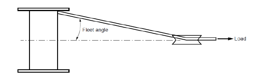
Figure 2.2.1 Fleet angle
The dimensioning of the winch drum should take into account the rope bending
specifications provided by the towline manufacturer.
Due consideration should be given to the proper spooling of the towline on the winch
drum, as well as preventing the towline slipping over the flanges of the drum.
Towing winches may be equipped with an active pay-out and haul-in system
automatic adjustment of towline. In such a case, the relevant requirements of Ch 2, 2.3 Towing arrangements for Escort Tugs 2.3.6 and Ch 2, 2.3 Towing arrangements for Escort Tugs 2.3.8 should be complied with.
It is recommended that the towing winch should be fitted with equipment to
continuously measure the tension (mean tension, tension peaks and slack line events)
in the towline.
In case a towline measurement system is installed on board, the measured data should
be displayed on the bridge.
2.2.6 Guidelines on testing of towing winches
The following guidelines outline the appropriate testing regimes for towing winches
installed on board tugs.
Towing winches, including the associated emergency quick-release devices
should be load tested at the DL, as defined in Ch 2, 2.2 Towing arrangements for Tugs 2.2.3, or the BHL, as defined in Ch 1, 1.3 Definitions 1.3.5, whichever is the
greatest. Generally, load testing should be conducted at a specialised facility
equipped to generate the required line tension (e.g. maker’s premises) and witnessed
by Lloyd’s Register.
In case a towing winch is of conventional, proven design, for which load testing has
been previously performed in a manner deemed acceptable by Lloyd’s Register
(evidence and results of load testing should be supplied), it may be sufficient to
perform on board function testing in accordance with the guidelines specified
below.
The proper functioning of the towing equipment should be verified by on
board testing witnessed by Lloyd’s Register. Function testing should be performed
both for normal operating conditions in accordance with the towing arrangement plan
(see
Ch 2, 2.2 Towing arrangements for Tugs 2.2.2) and for emergency conditions (emergency quick-release, failure of
main power supply). The safe operation of the towing winch from all control stations
should be demonstrated.
Towing winches should be function tested on board. The correct
functioning of the winch brake, the load carrying winch components and the
associated supporting structure should be demonstrated at a towline force equal to
the bollard pull, as defined in Ch 1, 1.3 Definitions 1.3.1. The emergency quick-release
should be function tested under normal power supply conditions with a towline force
corresponding to the minimum thrust (engine(s) clutched in and running at idle
speed), as well as in a dead-ship condition (without strain in the towline).
Winch operating modes which should be function tested include hauling in and paying
out of the towline, as well as braking.
Hydraulic and electrical systems should be function tested on board in accordance
with Lloyd’s Register’s requirements for machinery and electrical systems.
Operational tests should be performed by the crew in order to ensure the satisfactory
operation of the towing equipment, in particular the emergency quick-release
systems, as requested by the operating manual.
Records of operational tests are should be kept on board and made available to
Lloyd’s Register upon request.
2.2.7 Design requirements for towline guiding fittings
The Rules mandate that the towline guiding fittings, such as fairleads,
staples, gob-eyes, towing pins, stern rollers and equivalent components which guide
the towline, are able to sustain the force exerted by the towline loaded under a
tension equal to the DL, in the most unfavourable anticipated position of the
towline without exceeding the following stress level criteria:
- Normal stress σ ≤ 0,75σref;
- Shear stress σ ≤ 0.47σref;
- Equivalent stress σe ≤ 0,85σref,
where
- σref: Reference stress of the material, in
N/mm2, normally to be taken as
 , but may be taken as σy for
fittings not made of welded construction; , but may be taken as σy for
fittings not made of welded construction;
- k: Material factor, defined as function of the minimum
guaranteed yield stress σy, see
Table 2.2.2 Material factor k.
Table 2.2.2 Material factor k
| σy
(N/mm2)
|
k
|
| 235
|
1
|
| 315
|
0,78
|
| 355
|
0,72
|
| 390
|
0,68
|
In addition, towline guiding fittings used for guiding the towline when towing on a
towing winch must be able to sustain the force exerted by the towline loaded under a
tension equal to the BHL of the associated winch in the most unfavourable
anticipated position of the towline without exceeding the above-mentioned stress
level criteria.
Finally, where a towline guiding fitting (e.g. fairlead or guide pin) has been
designed for a specific Safe Working Load (SWL), defined as the maximum static
working load, the fitting should be able to sustain a force equal to 2 times the SWL
without exceeding the above-mentioned stress level criteria.
2.2.8 Additional design guidance for towline guiding fittings
In addition to the Rule requirements outlined in Ch 2, 2.2 Towing arrangements for Tugs 2.2.7, the following
design guidelines should be followed.
When considering the above design checks for the strength of towline guiding
fittings, at the discretion Lloyd’s Register, where the yielding check of the
towline guiding fittings is carried out by means of a three-dimensional finite
element model, an increase of the permissible stress levels given above by 10 per
cent (compared to a beam model) will be specially considered.
Sizing and radiusing of towline guiding fittings should be appropriate to prevent
fretting or abrasion of any towlines.
All towline guiding fittings should be regularly checked and maintained to ensure
their condition does not affect smooth carriage of the towline.
The placement of towline guiding fittings should be such that they do not cause undue
friction or bending beyond the specified limits of the towline manufacture.
Adequate towline guiding fittings should be supplied and arranged to effectively lead
and restrain the towline within the designed limits of its sweep.
Towing guiding fittings should generally be arranged in such a position (noting the
position of towing equipment and towline path) as to minimise heeling moment due to
the towline force.
2.2.9 Design requirements for towing hooks
The classification Rules require that towing hooks and their load carrying
attachments (connecting the towing hook to the hull structure) must be able to
sustain the DL without exceeding an equivalent stress level (based on von Mises
criterion) of 0.80σy.
The supporting calculations to demonstrate this are to be provided to Lloyds Register
and must consider the DL being applied in the most unfavourable anticipated position
for the structure.
2.2.10 Additional design guidance for towing hooks
In addition to the mandatory Rule requirements the following additional guidance
should be complied with.
Towing hooks should be provided with an emergency quick-release device operable from
a position on the bridge with full view and control of the towing operation, as well
as at a location near the hook where the device can be safely operated. Identical
means of control for the emergency quick-release devices should be provided at each
control station and are to be protected against unintentional use.
The force necessary to open the hook under load should not be greater than 150 N.
The applicable procedures for the emergency quick-release device should be
communicated to the crew and vital information should be displayed next to the
control desk or another appropriate location.
Towing hooks should generally be arranged in such a position (noting the position of
towline guiding fittings and towline path) as to minimise heeling moment due to the
towline force.
2.2.11 Guidelines on testing of towing hooks
The following guidelines outline the appropriate testing regimes for towing hooks
installed on board tugs.
Towing hooks, including the associated emergency quick-release devices,
should be load tested to the DL, as defined in Ch 2, 2.2 Towing arrangements for Tugs 2.2.3, at a specialised facility equipped to generate the required line
tension (e.g. maker’s premises) and witnessed by Lloyd’s Register.
In case a towing hook is of conventional, proven design, for which load testing has
been previously performed in a manner deemed acceptable by Lloyd’s Register,
(evidence and results of load testing should be supplied), it may be sufficient to
perform on board function testing in accordance with the guidelines specified
below.
The proper functioning of the towing equipment should be verified by on
board testing witnessed by Lloyd’s Register. Function testing should be performed
both for normal operating conditions in accordance with the towing arrangement plan
(see
Ch 2, 2.2 Towing arrangements for Tugs 2.2.2) and for emergency conditions (emergency quick-release, failure of
main power supply). The safe operation of the towing hook from all control stations
should be demonstrated.
Towing hooks should be function tested on board. The correct functioning
of the hook and the associated supporting structure should be demonstrated at a
towline force equal to the bollard pull, as defined in Ch 1, 1.3 Definitions 1.3.1. The emergency quick-release
should be function tested under normal power supply conditions with a towline force
corresponding to the minimum thrust (engine(s) clutched in and running at idle
speed), as well as in a dead-ship condition (without strain in the towline).
Operational tests should be performed by the crew in order to ensure the satisfactory
operation of the towing equipment, in particular the emergency quick-release
systems, as requested by the operating manual.
Records of operational tests are should be kept on board and made available to
Lloyd’s Register upon request.
2.2.12 Design requirements for towing equipment supporting structures
The Classification Rules require that the supporting structures of
towing equipment should be able to sustain the load exerted on the supporting
structure under the action of the towline loaded under a tension equal to the DL in
the most unfavourable anticipated position of the towline, without exceeding the
stress level criteria:
- Normal stress σ ≤ 0,75σref;
- Shear stress σ ≤ 0.47σref;
- Equivalent stress σe ≤
0,85σref,
where
- σref: Reference stress of the material, in N/mm2,
normally to be taken as
 , but may be taken as σy for
fittings not made of welded construction; , but may be taken as σy for
fittings not made of welded construction;
- k: Material factor, defined as function of the minimum
guaranteed yield stress σy, see
Table 2.2.2 Material factor k.
In addition, the supporting structures of towing equipment engaged for
escort operations or when towing on a towing winch must be able to sustain the load
exerted on the supporting structure under the action of the towline loaded under a
tension equal to the BHL of the associated winch, as specified in Ch 1, 1.3 Definitions 1.3.5, in the most unfavourable
anticipated position of the towline without exceeding the stress level criteria
specified above.
Also, where a towline guiding fitting has been designed for a specific SWL, defined
as the maximum static working load, the associated supporting structure should be
able to sustain a force equal to 2 times the SWL without exceeding the stress level
criteria specified above.
2.2.13 Additional design guidelines for towing equipment supporting structure
In case the yielding check of the towing equipment supporting structures is carried
out by means of a threedimensional finite element model, increase of the permissible
stress levels given above by 10 per cent (compared to a beam model) will be
specially considered by Lloyd’s Register.
Care should be taken that if towing equipment supporting structure is also exposed to
other loads (e.g. weather deck loadings ) in combination with the with loads from
towing, then these additional loads should be superimposed into the strength
assessment in order to produce the most conservative case for analysis.
2.2.14 Additional design guidelines for winch emergency release systems
The emergency release system should be operable under all normal and reasonably
foreseeable abnormal conditions (these may include, but are not limited to, the
following: vessel electrical failure, extreme list/trim angles, load applied at the
limits of operating load, fleet angle, variable load (for example due to heavy
weather), etc.).
Emergency release systems should allow the winch drum to rotate and allow the towline
to pay out in a controlled manner.
An alternative source of energy should also be provided such that normal operation of
the emergency release system can be sustained under dead-ship conditions for at
least three complete emergency release system operations of the most demanding winch
connected to it.
Where the winch design is such that the brake is applied by spring tension and
released using hydraulic or pneumatic power, sufficient power should be provided to
operate the emergency release system, in a dead-ship situation, for a minimum of
five minutes. This may be reduced to the time required for the full length of the
towline to feed off the winch drum at the minimum load as specified below if this is
less than five minutes, noting that after the emergency release system has been
activated it is considered good practice for the brake to first completely open and
then automatically tighten slightly to ensure a controlled release of the
towline.
The emergency release system should function as quickly as reasonably practicable and
within a maximum of three seconds after activation.
Arrangements should ensure that when emergency release system is activated, there is
sufficient resistance to rotation to avoid uncontrolled unwinding of the towline
from the drum.
The towline load required to rotate the winch drum should be no greater than:
- the lesser of five tonnes or five per cent of the maximum BHL of the
associated winch when two layers of towline are on the drum,
or
- 15 per cent of the BHL of the associated winch where it is demonstrated that
the resistance to rotation does not exceed 25 per cent of the force that
will result in listing sufficiently to immerse of the lowest unprotected
opening.
The emergency release system should be capable of operating at 100 per cent of the
BHL of the associated winch.
Emergency release operation should be possible from the bridge and from the winch
control station on deck. The winch control station on deck should also be in a safe
location.
The emergency release control should be located in close proximity to the emergency
stop button for winch operations and both should be clearly identifiable, clearly
visible, and easily accessible and positioned to allow safe operability.
The emergency release function should take priority over any emergency stop function.
Activation of the winch emergency stop from any location should also not inhibit
operation of the emergency release system from any location.
Emergency release system control buttons are should be of the 'lock-in' type or
require positive action to cancel.
Controls for emergency use should be protected against accidental use.
The following emergency release system alarms and indications should be provided on
the bridge:
- Low fluid pressure in the control system
- Low accumulator/air pressure
- Low battery voltage (separate alarm and indication not required where
electrical power is supplied from the tug's emergency batteries).
Wherever practicable, control of the emergency release system should be provided by a
hard-wired system, fully independent of programmable electronic systems.
Programmable electronic systems that operate or may affect the control of emergency
release systems should generally be considered as safety critical/ essential
systems.
The emergency release system reset function should be always available from the
bridge regardless of the activation location and without manual intervention on the
working deck.
2.2.15 Guidelines on testing of winch emergency release systems
For each emergency release system or type thereof, should be verified either at the
manufacturer's works or as part of the commissioning of the towing winch when it is
installed on board. Where verification solely through testing is impractical (e.g.
due to health and safety), testing may be combined with inspection, analysis or
demonstration will be considered by Lloyd’s Register on a case-by-case basis.
The performance capabilities of the emergency release system should be documented and
made available on board the ship on which the winch has been installed.
The full functionality of the emergency release system should be tested as part of
the shipboard commissioning trials to the satisfaction of the Surveyor. Testing may
be conducted either during a Bollard Pull test or by applying the towline load
against a strong point on the deck of the tug that is certified to the appropriate
load.
For novel designs the emergency release systems should also be load tested with the
towline at an upward angle of 45 degrees with the horizontal plane at a towline
force of not less than 50 per cent of the design bollard pull.
2.2.17 Additional design guidelines for towlines
In addition to the Classification Rule requirements the following design guidelines
should be followed.
The breaking strength of towlines should be in accordance with appropriate industry
standards for marine operations, but not less than the appropriate DL.
In addition, the breaking strength of towlines used on a towing winch should not be
less than the BHL of the associated winch (see
Ch 1, 1.3 Definitions 1.3.5).
The towline should be protected from being damaged by chafing and abrasion. To this
end cargo rails, bulwarks, and other elements, supporting the towline should be
sufficiently rounded with consideration to the bend radius limit of the towline in
order to ensure that that the towline breaking strength is maintained.
The total length of the towline applied on a towing winch is to be such that under
normal operation at least half a layer remains on the drum. In no case should less
than three turns remain on the drum during normal operation.
2.3 Towing arrangements for Escort Tugs
2.3.2 Materials used in towing equipment should comply with the applicable class
requirements for materials. Class certificates are generally required for the
materials used for winch drums, drum shafts, winch brake components, winch
supporting frames, towing hooks and towline guiding fittings installed upon classed
vessels.
2.3.4 Documents to be submitted
In order for the plan appraisal of the towing equipment and the associated
foundations to be undertaken, the following documents should be submitted for
appraisal (Assuming no Type Approval is in place):
- Drawings of towing winches, including winch drums, main shaft, load carrying
non-rotating structures (support frame), winch brakes. Gear and clutch
information is also to be submitted for information;
- Hydraulic, electrical and control system diagrams of the towing winch, as
applicable (note that this may be used for information as required);
- Drawings of the towline guiding fittings used for escorting;
- Drawings of foundations and under deck supporting structures (clearly
showing reinforcements) of towing equipment including scantlings and
attachment methods as appropriate.
In addition to the above and to further facilitate the plan appraisal the follow may
be supplied to Lloyd’s Register for information:
- Escort towing arrangement plan, showing the location and general layout of
the towing equipment used for escorting, the range of anticipated lines of
action of the towlines with the associated maximum steady towline forces
(also known as the quasi-static towline force) and the corresponding points
of application of the towline forces on the towing equipment;
- Summary tables of maximum steering force Fs, in kN, and
maximum braking force Fb, in kN, for the intended range of
speeds VY, in kn, (In case the final values are not yet
available, estimated values may be submitted as preliminary information for
the purposes of an initial design review. Where a discrepancy between the
final values and the preliminary values exists, the drawings may need to be
re-reviewed against the final values);
- Arrangement drawings of the escort winch and towline guiding fittings used
for escorting (fairlead, staple etc);
- Design information of escort winch, including maximum rated line pull, winch
brake holding force, rendering and recovering loads and specification of
emergency quick-release arrangement
- Design calculations of escort winch, including winch drums, main shaft, load
carrying non-rotating structures (support frame) and braking capacity;
- Design load of towline guiding fittings used for escorting;
- Design calculations of the towline guiding fittings and the supporting
structures of towing equipment used for escorting, including detailed
analysis reports in case three-dimensional finite element models have been
used.
Additionally, where deemed necessary by Lloyd’s Register, buckling and/or fatigue
analysis, performed in accordance with a standard or code of practice recognised by
Lloyd’s Register, may be required to be submitted for information.
In case the final values are not yet available, estimated values may be submitted as
preliminary information for the purposes of an initial design review. In case the
discrepancy between the final values and the preliminary values, the drawings may
need to be re-reviewed against the final values.
2.3.5 Consideration of the design load
One of the critical factors in the design appraisal of the towing
equipment used for escort and its foundations is the design load (DL) that should be
considered for the strength assessment. This is outlined in the Rules and also given
in Table 2.2.3 Design loads: escort
tug of this guidance for easy reference
Table 2.2.3 Design loads: escort
tug
| Maximum steady towline force
Ft,MAX [kN]
|
Design ,load, DL [kN]
|
| General
|
Protected waters
|
| T ≤ 500
|
[3]T
|
[2,4]T
|
| 500 < T < 1000
|
[(2000 − T)/500]T
|
[(2000 − T)/625]T
|
| T ≥ 1000
|
[2]T
|
[1,6]T
|
The DL (in the Rules and in the table) take into consideration the
assumed dynamic effects through the application of the dynamic amplification factor
(DAF) which is clearly designated in square brackets in Table 2.2.3 Design loads: escort
tug (see also
Ch 1, 1.3 Definitions 1.3.4).
2.3.6 Design requirements for escort winches
The Rules require that the scantlings for escort winches (including winch drums, drum
shafts, brakes, support frames and connections to the hull structure) are to be
determined by direct calculations using the Design Loads (outlined in Table 2.2.3 Design loads: escort
tug)
The calculations should demonstrate that the escort winches (in particular the
components which are exposed to the tension in the towline, such as the winch drums,
drum shafts, brakes, support frame and connection to the hull structure) are able
to:
- sustain the DL, without permanent deformation, and;
- sustain the BHL, (as defined in Ch 1, 1.3 Definitions 1.3.5), without exceeding an
equivalent stress level (based on von Mises criterion) of
0,80σy;
- sustain the loads for the RP condition, as foreseen by the designer, without
exceeding an equivalent stress level (based on the von Mises criterion) of
0,40σy.
where
- σy : Minimum specified yield stress of material, in
N/mm2;
- RP: Is the Rated Pull i.e. the winch maximum hauling in load at the first
inner layer.
In each calculation case the most unfavourable anticipated position of the
towline should be considered.
2.3.7 Additional design guidance for escort winches
In addition to the Rule requirements outlined in Ch 2, 2.3 Towing arrangements for Escort Tugs 2.3.6, the following design guidelines should be followed.
Winches should be provided with an emergency quick-release device operable from a
position on the bridge with full view and control of the towing operation. Means of
control for the emergency quick-release device should be protected against
unintentional use.
Escort winches should generally be arranged in such a position (noting the position
of towline guiding fittings and towline path) as to minimise heeling moment due to
the towline force.
The winch brake should normally act directly on the drum and should be operable
(either manually or otherwise) in case of failure of the primary power supply
system.
The dimensioning of the winch drum should take into account the rope bending
specifications provided by the towline manufacturer.
Due consideration should be given to preventing the towline slipping over the flanges
of the drum.
Escort winches intended to be used in conditions where dynamic oscillations of the
towline are likely to occur, such as in open sea areas or other areas exposed to
waves, should be equipped with an active pay-out and haul-in system. This system
should automatically and reliably pay-out the towline in a controlled manner when
the towline force exceeds a 23 pre-set (adjustable) level equal to 110 per cent of
the rated towline force Ft,R ,and as the towline force is reduced,
actively haul-in the towline to prevent slack-line events thereby maintaining a
pre-set or adjustable towline force consistent with the rated towline force.
Pay-out and haul-in speeds and pull capability should be chosen taking into account
the anticipated escort services and the dynamic characteristics of the escort
tug.
Escort operations in conditions where dynamic oscillations of the towline are likely
to occur should not be based on the use of the brakes of the winch drum.
Escort operations performed by escort tugs with the service restriction notation
protected waters and any escort operation in calm water conditions, such as in ports
and sheltered waters, may be based on the use of the brakes of the winch drum. As a
minimum, the winch brake holding load (BHL) should be equal to or greater than two
times the maximum steady towline force Ft,MAX.
Escort winches should be fitted with equipment to continuously measure the tension in
the towline. The measured data should be displayed in the wheelhouse next to the
control desk or another appropriate location.
The escort towing system should be designed so as to enable the proper spooling of
the towline when hauling in. Generally this can be achieved by a suitable design of
the fairlead or staple guiding the towline between the escort winch and the assisted
ship.
Where a spooling device is fitted, it should be designed for the same
design load and stress criteria as the towline guiding fittings, see
Ch 2, 2.2 Towing arrangements for Tugs 2.2.7.
2.3.8 Guidelines on testing of escort winches
The following guidelines outline the appropriate testing regimes for escort winches
installed on board escort tugs.
Escort winches, including the associated emergency quick-release device
should generally be load tested to the DL, as defined in Ch 2, 2.2 Towing arrangements for Tugs 2.2.5, or the BHL, as defined in Ch 1, 1.3 Definitions 1.3.5, whichever is the
greatest. Generally, load testing should be conducted at a specialised facility
equipped to generate the required line tension (e.g. maker’s premises) and witnessed
by Lloyd’s Register.
In case an escort winch is of conventional, proven design, for which load testing has
been previously performed in a manner deemed acceptable by Lloyd’s Register
(evidence and results of load testing should be supplied), it may be sufficient to
perform on board function testing in accordance with the requirements specified
below.
The proper functioning of the towing equipment used for escort services
should be verified by on board testing witnessed by Lloyd’s Register. Function
testing should be performed both for normal operating conditions in accordance with
the escort towing arrangement plan, seeCh 2, 2.3 Towing arrangements for Escort Tugs 2.3.4, and
for in emergency conditions (emergency quick-release, failure of main power supply).
The safe operation of the escort winch from all control stations should be
demonstrated.
Escort winches should be function tested on board. The correct
functioning of the winch brake, the load carrying winch components and the
associated supporting structure should be demonstrated at a towline force equal to
the bollard pull, as defined in Ch 1, 1.3 Definitions 1.3.1. The emergency quick-release
should be function tested under normal power supply conditions with a towline force
corresponding to the minimum thrust (engine(s) clutched in and running at idle
speed), as well as in a dead-ship condition (without strain in the towline).
Winch operating modes which should be function tested include hauling in and paying
out of the towline, braking and the active pay-out and haul-in system when
fitted.
Hydraulic and electrical systems should be function tested on board in accordance
with Lloyd’s Register’s requirements for machinery and electrical systems.
Operational tests should be performed by the crew in order to ensure the satisfactory
operation of the towing equipment used for escort services, in particular the
emergency quick-release systems, as requested by the operating manual.
Records of operational tests should be kept on board and made available to Lloyd’s
Register upon request.
2.3.9 Design requirements for towline guiding fittings
The Rules mandate that the towline guiding fittings used for escort services, such as
fairleads, staples, and equivalent components which guide the towline, are able to
sustain the force exerted by the towline loaded under a tension equal to the DL, in
the most unfavourable anticipated position of the towline without exceeding the
following stress level criteria:
- Normal stress σ ≤ 0,75σref;
- Shear stress σ ≤ 0.47σref;
- Equivalent stress σe ≤ 0,85σref,
where
- σref : Reference stress of the material, in
N/mm2, normally to be taken as
 , but may be taken as σy for
fittings not made of welded construction; , but may be taken as σy for
fittings not made of welded construction;
- k: Material factor, defined as function of the minimum
guaranteed yield stress σy,
Table 2.2.4 Material factor k
| σy (N/mm2)
|
k
|
| 235
|
1
|
| 315
|
0,78
|
| 355
|
0,72
|
| 390
|
0,68
|
In addition, towline guiding fittings should be able to sustain the force exerted by
the towline loaded under a tension equal to the BHL of the associated winch in the
most unfavourable anticipated position of the towline without exceeding the
above-mentioned stress level criteria
Finally, where a towline guiding fitting has been designed for a specific Safe
Working Load (SWL), defined as the maximum static working load, the fitting should
be able to sustain a force equal to 2 times the SWL without exceeding the
above-mentioned stress level criteria.
2.3.10 Additional design guidance for towline guiding fittings
In addition to the Rule requirements out lined in Ch 2, 2.2 Towing arrangements for Tugs 2.2.7, the following design guidelines should be followed.
When considering the aforementioned design checks for the strength of towline guiding
fittings, at the discretion Lloyd’s Register, where the yielding check of the
towline guiding fittings is carried out by means of a three-dimensional finite
element model, an increase of the permissible stress levels given above by 10 per
cent (compared to a beam model) will be specially considered.
Sizing and radiusing of towline guiding fittings should be appropriate to prevent
fretting or abrasion of any towlines.
All towline guiding fittings should be regularly checked and maintained to ensure
their condition does not affect smooth carriage of the towline.
The placement of towline guiding fittings should be such that they do not cause undue
friction or bending beyond the specified limits of the towline manufacture.
Adequate towline guiding fittings should be supplied and arranged to effectively lead
and restrain the towline within the designed limits of its sweep.
2.3.11 Design requirements for towing equipment supporting structures
The Classification Rules require that the supporting structures of towing
equipment should be able to sustain the load exerted on the supporting structure
under the action of the towline loaded under a tension equal to the DL in the most
unfavourable anticipated position of the towline, without exceeding the stress level
criteria:
- Normal stress σ ≤ 0,75σref;
- Shear stress σ ≤ 0.47σref;
- Equivalent stress σe ≤ 0,85σref,
where
- σref : Reference stress of the material, in N/mm2,
normally to be taken as
 , but may be taken as σy for
fittings not made of welded construction; , but may be taken as σy for
fittings not made of welded construction;
- k : Material factor, defined as function of the minimum guaranteed yield
stress σy, see
Table 2.2.4 Material factor k.
In addition, the supporting structures of towing equipment engaged for
escort operations must be able to sustain the load exerted on the supporting
structure under the action of the towline loaded under a tension equal to the BHL of
the associated winch, as specified in Ch 1, 1.3 Definitions 1.3.5, in the most unfavourable
anticipated position of the towline without exceeding the stress level criteria
specified above.
Also, where a towline guiding fitting has been designed for a specific SWL, defined
as the maximum static working load, the associated supporting structure should be
able to sustain a force equal to 2 times the SWL without exceeding the stress level
criteria specified above.
2.3.12 Additional design guidelines for towing equipment supporting structure
In case the yielding check of the towing equipment supporting structures is carried
out by means of a threedimensional finite element model, increase of the permissible
stress levels given above by 10 per cent (compared to a beam model) will be
specially considered by Lloyd’s Register.
Care should be taken that if towing equipment supporting structure is also exposed to
other loads (e.g. weather deck loadings ) in combination with the with loads from
towing, then these additional loads should be superimposed into the strength
assessment in order to produce the most conservative case for analysis.
2.3.13 Additional design guidelines for winch emergency quick-release systems
The emergency quick-release device should be capable of releasing the towline under
the maximum anticipated load regardless of the angle of the towline and the tug’s
trim and heel. This device should be operable from a position on the bridge with
full view and control of the towing operation.
The emergency quick- release system should be operable under all normal and
reasonably foreseeable abnormal conditions (these may include, but are not limited
to, the following: vessel electrical failure, extreme list/trim angles, load applied
at the limits of operating load, high fleet angle, variable load (for example due to
heavy weather), etc.).
Means of control for the emergency quick-release device should be protected against
unintentional use.
The time delay between the initiation and actual start of the emergency quick-release
(pay-out of the towline) should be as short as reasonably practicable.
The speed of paying out should be such that the tension in the towline is reduced as
fast as reasonably possible, taking into consideration that paying out should be in
a controlled manner. To that end effective means to prevent spinning (free,
uncontrolled rotation) of the winch drum should to be provided as spinning of the
winch drum could cause the towline to get stuck and disable the release function of
the winch.
After a quick-release event the winch brakes should be able to operate normally
(automatically), while the winch motor should be engaged manually (not
automatically).
The applicable procedures for the emergency quick-release device, including time
delays and release speed, should be communicated to the crew and such vital
information should be displayed next to the control desk or another appropriate
location.
2.3.14 Guidelines on testing of winch emergency release systems
For each emergency release system or type thereof, should be verified either at the
manufacturer's works or as part of the commissioning of the escort winch when it is
installed on board. Where verification solely through testing is impractical (e.g.
due to health and safety), testing may be combined with inspection, analysis or
demonstration will be considered by Lloyd’s Register on a case-by-case basis.
The performance capabilities of the emergency release system should be documented and
made available on board the ship on which the winch has been installed.
The full functionality of the emergency release system should be tested as part of
the shipboard commissioning trials to the satisfaction of the Surveyor. Testing may
be conducted either during a Bollard Pull test or by applying the towline load
against a strong point on the deck of the tug that is certified to the appropriate
load.
For novel designs the emergency release systems should also be load tested with the
towline at an upward angle of 45 degrees with the horizontal plane at a towline
force of not less than 50 per cent of the design bollard pull.
2.3.16 Additional design guidelines for towlines
In addition to the Classification Rule requirements the following design guidelines
should be followed.
The breaking strength of towlines should be in accordance with appropriate industry
standards for marine operations, but not less than the appropriate DL.
In addition, the breaking strength for towlines used for escort services
on an escort winch should not be less than the BHL of the associated winch
(see
Ch 1, 1.3 Definitions 1.3.5)
The towline should be protected from being damaged by chafing and abrasion. To this
end cargo rails, bulwarks, and other elements, supporting the towline should be
sufficiently rounded with consideration to the bend radius limit of the towline in
order to ensure that that the towline breaking strength is maintained.
It is recommended that the total length of the towline applied on a towing winch is
to be such that under normal operation at least half a layer remains on the drum. In
no case should less than three turns remain on the drum during normal operation.
2.3.17 Additional recommended equipment for Escort tugs
Escort tugs should be equipped with a calibrated heeling angle measurement system
(inclinometer).
The measured heeling angle should be displayed in the wheelhouse next to the control
desk or another appropriate location where the readout is prominent.
2.4 Fendering
2.4.2 Design requirements for Fenders
The Rules stipulate that ‘An efficient fender is to be fitted to the ship's side at
deck level extending all fore and aft’.
2.4.3 Additional design guidelines for Fenders
The following additional guidance should be applied with respect to the fendering
arrangements for tugs.
A robust and efficient fendering system should be fitted in all areas intended for
pushing. The purpose of the fendering system is to distribute the pushing force and
limit its dynamic component on the hull structure of both the tug and the assisted
ship.
The design of the fendering system, in particular the contact area and stiffness
distribution, should result in an acceptable pressure distribution on the supporting
structure of the tug (and the assisted ship) under the maximum anticipated loads
during pushing operations.
The design load (DL) to be considered for the strength assessment of the fender
supporting structure may be taken as follows:
The DL takes into consideration anticipated dynamic effects through the application
of the DAF (designated in square brackets in the formula) in but not bouncing
effects.
The fender supporting structure should be able to sustain the DL, as specified above,
without exceeding the following stress level criteria.
- Normal stress σ ≤ 0,75σref;
- Shear stress σ ≤ 0.47σref;
- Equivalent stress σe ≤ 0,85σref,
where
- σref : Reference stress of the material, in N/mm2,
normally to be taken as
 , but may be taken as σy for
fittings not made of welded construction; , but may be taken as σy for
fittings not made of welded construction;
- k : Material factor, defined as function of the minimum guaranteed
yield stress σy, see
Table 2.2.4 Material factor k.
Note, within the context of this guidance note, it is considered that during pushing
operations the contact between the tug and assisted ship is maintained and that no
bouncing (e.g. under wave action) is taking place as it is understood that pushing
operations are normally halted when bouncing starts to occur due to operational
difficulties in keeping position within the pushing area of the assisted ship as
well as controlling the associated impact type loads.
Therefore forces resulting from bouncing loads are not considered, if this assumption
is not valid for the design and the operational profile of the vessel then these
dynamic forces are should be included in any fendering calculations. Calculations of
the additional forces and their application to the design should be forwarded to
Lloyd’s Register at the earliest possible convenience for timely consideration.
2.5 Escort operation performance numeral and trials
2.5.1 For Escort tugs, Lloyd’s Register offers the specific notations EPN (F,B,V,C)
and CFD EPN (F,B,V) to denote the escort performance numeral of the vessel.
In the case of EPN the escort performance numeral is obtained by full scale
testing and for CFD EPN it is obtained through CFD.
The EPN is made up of a series of values, i.e. (F,B,V,C). These are defined as:
- F: Maximum steering force, in tonnes.
- B: Maximum braking force, in tonnes.
- V: Speed, in knots, at which F and B are determined.
- C: Time, in seconds, required for the escort tug in manoeuvring from
maintained oblique position of the tug giving it a maximum steering force on
one side of the assisted vessel to a mirror position on the other
side.
Where escort performance numerals are predicted using computational fluid dynamics,
the escort performance numeral ‘C’ is omitted
2.6 Anchoring equipment
2.6.2 Additional design guidelines for anchors
The design of all anchor heads should be such so as to minimise stress
concentrations, and in particular, the radii on all parts of cast anchor heads
should be as large as possible, especially where there is considerable change of
section.
Anchors which must be specially laid the right way up, or which require the fluke
angle or profile to be adjusted for varying types of sea bed, will not generally be
considered for normal ship use.
The number of anchors and chain cables which should be carried should
generally be in line with the aforementioned Table 13.7.1 Equipment requirements of the Rules and Regulations for the Classification of Ships, July 2022. However for vessels with the type
notation tug which are limited to operations within protected waters or
extended protected waters Lloyd’s Register will specially consider a reducing the
required number of required anchors and chain cables to 1.
Lloyds Register may further specially consider a reduction of the number of anchors
and chain cables as depicted in Table 2.2.5 Reduced number of anchors and chain cables based on redundancy
principles. Basis of this consideration will
be the service and operational restrictions of the vessel and the levels of
redundancy on board, for example:
- The tug is equipped with at least twin propulsion, of which each main engine
can maintain sufficient propulsion power to safely return to berth. For this
purpose, the main engines should be able to run self-supporting, i.e.
independent of generator sets intended for auxiliary power, unless these are
able to run parallel and, in case of black-out, have automatic starting and
connecting to switchboard within 45 seconds;
- A single failure, except fire, should not cause total propulsion failure;
- A fixed fire-fighting installation is provided.
Table 2.2.5 Reduced number of anchors and chain cables based on redundancy
principles
| Type notation
|
Service restriction notation
|
Nr
|
| Tug
|
Protected waters/Extended protected
waters
|
0
|
| Tug
|
Specified coastal service, or Specified
operating or service areas
|
1
|
| Tug
|
(unrestricted)
|
2
|
| Escort tug
|
Any
|
1
|
| Escort tug
|
(unrestricted)
|
2
|
Lloyd’s register will specially consider the case where a spare anchor is supplied as
an alternative to a second bower anchor. In such cases special provisions, such as a
crane and suitable storage space for the spare anchor, should be present on
board.
For tugs with a service restriction notation denoting that they are restricted to
operations within protected waters or extended protected waters, effectively
operating in a fixed and limited area, Lloyd’s Register will specially consider the
case that the spare anchor is stored ashore.
2.7 Machinery and Electrotechnical systems
2.7.1 All mechanical and Electrotechnical systems are to be in compliance with the relevant
requirements within the Rules.
Which Rules are applicable to the vessel is dependent on the mechanical and
electrical outfit of the vessel.
2.8 Fire protection, detection and extinction
2.8.2 Both the Class Rules and statute stipulate that tugs of 500 gross tons
or more, on international voyages, where provision is made within International
Conventions, are to be provided with the fire safety measures required by the
International Convention for the Safety of Life at Sea, 1974, as amended.
In addition, the Class Rules stipulate that tugs of 500 gross tons or more employed
on national voyages are to comply with the fire safety measures prescribed and
approved by the Government of the Flag State.
2.8.3 For tugs of less than 500 gross tons The Rules and Regulations for the Classification of Ships, July 2022 also contain relevant requirements in
Pt 6, Ch 4, 2 Fire detection, protection and extinction. The
content of this section is within the spirit of the International Convention and
Protocol requirements for ships of Convention size. However it is to be noted that
the content of this section are “intended to apply to new and, as far as reasonable
and practicable, or as found necessary by the relevant Administration, to existing
cargo ships of less than 500 GT.”. As such, consideration will be given to the
acceptance of fire safety measures prescribed and approved by the Government of the
Flag State instead.
Ch 3, 3.1 Fire safety for tugs of less than 500 GT
of this document includes Lloyd’s Register supported fire protection, detection and
extinction minimum standard guidance.
|