
Section
2 Global hull girder loads
2.1 Introduction
2.1.1 This
section describes the calculation of global loads governing the design
of the hull girder where all three hulls are to be considered a part
of the hull girder. The structural effectiveness of the side hulls
is described in Vol 1, Pt 6, Ch 3 Global Strength Requirements.
2.1.2 The
still water bending moments and shear force distributions are to be
derived using a suitable direct calculation method for a range of
loading conditions which cover the operational envelope of the ship.
2.2 Still water bending moment
2.2.1 The
still water bending moment, M
sw, is the maximum
moment calculated from the loading conditions.
2.2.2 Still
water bending moments are to be calculated along the vessel's length.
For these calculations, downward loads are to be taken as positive
values and are to be integrated in the forward direction from the
aft end of L. Hogging bending moments are positive.
2.2.3 If the
vessel has low deadweight requirements and does not have a sag condition,
then the maximum sagging bending moment may be taken as the minimum
hogging bending moment.
2.3 Still water shear force
2.3.1 The
still water shear force, Q
sw, at each transverse
section along the vessel is to be taken as the maximum positive and
negative value found from the longitudinal strength calculations.
2.3.2 Still
water shear forces are to be calculated at each section along the
vessel's length. For these calculations, downward loads are to be
taken as positive values and are to be integrated in a forward direction
from the aft end of L
R. The shear force is
positive when the algebraic sum of all vertical forces aft of the
section is positive.
2.4 Vertical wave bending moment
2.4.1 The
vertical wave bending moment, M
w, at any position
along the length of the vessel is given by the following:

where
|
D
f
|
= |
0 at aft end of L
R, see
Figure 4.2.1 Vertical bending moment distribution factor, D
f
|
| = |
1 from  to to 
|
| = |
0 at forward end of L
R
|
|
M
o
|
= |
0,1L
f
f
serv
L
R
2
B
wl (C
b + 0,7)
|
|
L
f
|
= |
0,0412L
R + 4,0 for L
R ≤
90 m
|
| = |
10,75 –  for L
R > 90 m for L
R > 90 m
|
|
|
= |
For unrestricted service: |
|
f
serv
|
= |
1 |
|
|
= |
For restricted service: |
|
|
= |
If the Complementary Rules are the Rules and Regulations
for the Classification of Special Service Craft (hereinafter
referred to as the Rules for Special Service Craft)
|
|
f
serv
|
= |
G
f, see
Pt 5, Ch 5, 3.2 Vertical wave bending moments and associated shear forces of the Rules for
Special Service Craft
|
| = |
0,5 for G1 craft |
| = |
0,6 for G2 craft |
| = |
0,7 for G3 craft |
| = |
0,8 for G4 craft |
| = |
1,0 for G5 and G6 craft |
|
|
= |
If the Complementary Rules are the Rules and Regulations
for the Classification of Naval Ships (hereinafter referred
to as the Rules for Naval Ships)
|
|
f
serv
|
= |
f
s, see
Vol 1, Pt 5, Ch 2, 2.4 Service area factors of the Rules
for Naval Ships
|
|
F
f
|
= |
the hogging, F
fh, or sagging, F
fs, correction factor as follows:
|
|
F
fh
|
= |

|
|
F
fs
|
= |
1,10R
A
0,3 for values of R
A ≥ 1,0
|
|
F
fs
|
= |
–1,10 for values of R
A < 1,0
|
|
|
= |
where |
|
|
= |
C
b is defined in Vol 1, Pt 1, Ch 1, 5.2 Principal particulars but is not to be taken
as less than 0,6
|
|
|
= |
L
R and B
wl and
are defined in Vol 1, Pt 1, Ch 1, 5.2 Principal particulars
|
|
|
= |
D
f, x
sh, L
f, M
o, f
serv, F
f, F
fh, F
fs and R
A are defined in Vol 1, Pt 5, Ch 1, 1.4 Symbols and definitions
|
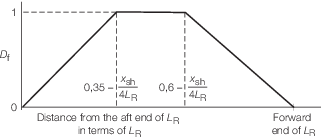
Figure 4.2.1 Vertical bending moment distribution factor, D
f
2.4.2 The
area ratio factor, R
A, for the combined stern
and bow shape is to be derived as follows:
2.4.3 The
bow flare area,A
BF, is illustrated in Figure 4.2.3 Derivation of bow and stern flare areas and may be derived as
follows:
Alternatively, the following formula may be used:
where
|
T
CU
|
= |

|
|
|
= |
For ships with large bow flare angles above the T
CU waterline, the bow flare area may need to be specially considered.
If T
CU occurs above the level of the main
deck, then the main deck is to be used.
|
|
|
= |
A
BF, A
UB, A
LB, b
0, b
1, b
2, a and T
CU are
defined in Vol 1, Pt 5, Ch 1, 1.4 Symbols and definitions.
|
|
|
= |
L
f is defined in Vol 1, Pt 5, Ch 4, 2.4 Vertical wave bending moment 2.4.1
|
|
|
= |
T is defined in Vol 1, Pt 1, Ch 1, 5.2 Principal particulars.
|
2.4.4 The
stern flare area, A
SF, is illustrated in Figure 4.2.3 Derivation of bow and stern flare areas and may be derived as
follows:
where
|
T
CL
|
= |

|
|
|
= |
If T
CL occurs below the baseline, then
the baseline is to be taken as T
CL. This may
result in a value of zero for the area A
LS
|
|
|
= |
A
SF, A
US, A
LS and T
CL are defined in Vol 1, Pt 5, Ch 1, 1.4 Symbols and definitions
|
|
|
= |
L
f is defined in Vol 1, Pt 5, Ch 4, 2.4 Vertical wave bending moment 2.4.1
|
|
|
= |
T is defined in Vol 1, Pt 1, Ch 1, 5.2 Principal particulars.
|
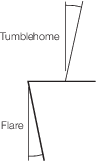
Figure 4.2.2 Tumblehome
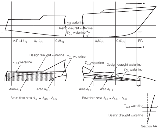
Figure 4.2.3 Derivation of bow and stern flare areas
2.4.5 For
ships with tumblehome in the stern region, see
Figure 4.2.2 Tumblehome, the maximum breadth
at any waterline less than T
CU is to be used
in the calculation of A
US. The effects of
appendages including bossings are to be ignored in the calculation
of A
LS.
2.5 Vertical wave shear force
2.5.1 The
wave shear force, Q
w, at any position along
the ship is given by:
where K
f is illustrated in Figure 4.2.4 Shear force distribution factor, K
f
and is to be taken as
follows:
-
Positive shear
force:
|
K
f
|
= |
0 at aft end of L
R
|
| = |
+0,836F
fH between  and and 
|
| = |
+0,65F
fH between  and and 
|
| = |
–0,65F
fS between and and 
|
| = |
–0,91F
fS between  and and 
|
| = |
0 at the aft end of L
R
|
-
Negative shear
force:
|
K
f
|
= |
0 at aft end of L
R
|
| = |
+0,836F
fS between  and and 
|
| = |
+0,65F
fS between  and and 
|
| = |
–0,65F
fH between  and and 
|
| = |
–0,91F
fH between  and and 
|
| = |
0 at the aft end of L
R
|
Intermediate values are to be determined by linear
interpolation.
M
o,F
fh and F
fs are defined in Vol 1, Pt 5, Ch 4, 2.4 Vertical wave bending moment 2.4.1
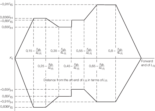
Figure 4.2.4 Shear force distribution factor, K
f
2.6 Horizontal bending moment
2.6.1 The
horizontal bending moment, M
h, is to be calculated
as follows:
2.7 Longitudinal torsional moment
2.7.1 The
longitudinal torsional moment, M
lt, illustrated
in Figure 4.2.5 Longitudinal torsional moment is to be calculated
as follows:
where
|
|
= |
T
f is defined in Figure 4.2.6 Longitudinal torsional moment distribution factor, T
f
.
|
|
|
= |
x
shaft, x
shfwd,
ρ, V
sh, V
cd, V
mhs and y
cs are defined in Vol 1, Pt 5, Ch 1, 1.4 Symbols and definitions.
|
|
|
= |
a
heave is defined in Vol 1, Pt 5, Ch 3, 2.2 Design accelerations.
|
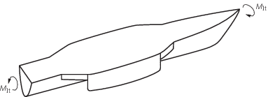
Figure 4.2.5 Longitudinal torsional moment
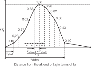
Figure 4.2.6 Longitudinal torsional moment distribution factor, T
f
2.8 Longitudinal hull girder design loads
2.8.1 The
total Rule vertical bending moment envelope, M
tot,
is to be taken as follows:
where M
sw and M
w are defined in Vol 1, Pt 5, Ch 4, 2.2 Still water bending moment and Vol 1, Pt 5, Ch 4, 2.4 Vertical wave bending moment, respectively, and are to take
into account the hogging and sagging conditions.
2.8.2 The
total Rule shear force envelope, Q
tot, is
to be taken as follows:
where Q
sw and Q
w are defined in Vol 1, Pt 5, Ch 4, 2.3 Still water shear force and Vol 1, Pt 5, Ch 4, 2.5 Vertical wave shear force, respectively, and are to take
into account the hogging and sagging conditions.
|