
Section
1 General
1.1 Application
1.1.1 The requirements
for longitudinal and transverse global strength for both mono-hull
and multi-hull craft of composite construction, are contained within
this Chapter. Due consideration is taken of the dynamic effects, where
appropriate, in both the crest and trough wave landing conditions.
1.2 Symbols and definitions
1.2.1 Unless
specified otherwise the symbols used in this Chapter are defined as
follows:
|
a
i
|
= |
cross sectional area of the individual ply, i,
in m2
|
|
E
i
|
= |
E
ti, or E
ci of
the individual ply i, relative to its position above
or below the neutral axis, in N/mm2
|
|
E
ci
|
= |
compressive modulus of individual ply, i, in N/mm2
|
|
E
ti
|
= |
tensile modulus of individual ply, i, in N/mm2
|
 i
i
|
= |
inertia of
the of individual ply, i, about the neutral axis, in
mm4
|
Σ(E
i
 i)H
i)H
|
= |
total
(E
 )H (stiffness) for the hull midship section,
in Nm4/mm2 )H (stiffness) for the hull midship section,
in Nm4/mm2
|
|
σci
|
= |
compressive
stress within an individual element, i, in N/mm2
|
|
σti
|
= |
tensile
stress within an individual element, i, in N/mm2
|
|
τH
|
= |
shear
stress at any position along the length of the craft, in N/mm2
|
|
x
i
|
= |
the distance to the centre of area of the individual ply, i,
from the outer surface of the keel plate laminate, in metres
|
|
y
i
|
= |
vertical distance from the hull transverse neutral axis to the
centre of the individual ply, in metres |
|
y
NA
|
= |
the distance of the neutral axis, from the outer surface of
the keel plate laminate, in metres |
L
R and B are
as defined in Pt 3, Ch 1, 6.2 Principal particulars.
1.2.2 The strength
deck is to be taken as follows:
-
Where there is a
complete upper deck the strength deck is the upper deck.
-
Where the upper deck
is stepped, as in the case of raised quarterdeck craft, the strength
deck is stepped as shown in Figure 6.1.1 Strength deck.
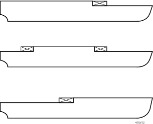
Figure 6.1.1 Strength deck
1.3 General
1.3.1 The additional
pressures arising from the influence of the global loading are considered
in the determination of the longitudinal strength requirements for
local and secondary stiffening and bottom shell laminate.
1.3.2 All continuous
longitudinal structural material is to be included in the calculation
of the stiffness, (E
 )H, of the hull midship section, and the lever, y
i, is to be measured vertically from the neutral
axis to the centre of the individual ply, i. The inertia
of an individual horizontal ply, i, about its own axes
is to be ignored. )H, of the hull midship section, and the lever, y
i, is to be measured vertically from the neutral
axis to the centre of the individual ply, i. The inertia
of an individual horizontal ply, i, about its own axes
is to be ignored.
1.3.3 Structural
members which contribute to the overall hull girder strength are to
be carefully aligned so as to avoid discontinuities resulting in abrupt
variations of stresses and are to be kept clear of any form of openings
which may affect their structural performance.
1.3.4 In general,
superstructures or deckhouses will not be accepted as contributing
to the global longitudinal or transverse strength of the craft. However,
where it is proposed to include substantial, continuous stiffening
members, special consideration will be given to their inclusion on
submission of the designer's/builder's calculations. Such calculations
are to make due allowance for superstructure efficiency. See
also
Pt 7, Ch 6, 2.5 Superstructures global strength.
1.3.5 Where continuous
deck longitudinals or deck girders are arranged above the strength
deck, special consideration may be given to the inclusion of their
sectional area in the calculation of the hull stiffness (E
 )H. The lever is to be taken to a position corresponding
to the depth of the longitudinal member above the moulded deckline
at side amidships. Each such case will be individually considered. )H. The lever is to be taken to a position corresponding
to the depth of the longitudinal member above the moulded deckline
at side amidships. Each such case will be individually considered.
1.3.6 Adequate
transition brackets are to be fitted at the ends of effective continuous
longitudinal strength members in the deck and bottom structures.
1.3.7 Scantlings
of all continuous longitudinal members of the hull girder based on
the minimum section stiffness requirements given in Pt 8, Ch 6, 2.2 Bending strength are to be maintained within 0,4L
R amidships. However, in special cases, based on consideration
of type of ship, hull form and loading conditions, the scantlings
may be gradually reduced towards the ends of the 0,4L
R part,
bearing in mind the desire not to inhibit the vessel's loading and
operational flexibility. L
R is as defined
in Pt 8, Ch 6, 1.2 Symbols and definitions 1.2.1.
1.4 Openings
1.4.1 Deck openings
having a length in the fore and aft directions exceeding 0,1B m
or a breadth exceeding 0,05B m, are always to be deducted
from the sectional areas used in the section stiffness calculation. B is as defined in Pt 8, Ch 6, 1.2 Symbols and definitions 1.2.1.
1.4.2 Deck openings
smaller than stated in Pt 8, Ch 6, 1.4 Openings 1.4.1 including
manholes, need not be deducted provided they are isolated and the
sum of their breadths or shadow area breadths (see
Pt 8, Ch 6, 1.4 Openings 1.4.3), in one transverse section does
not exceed 0,06 (B
1 - Σ b
1).
where
|
B
1
|
= |
breadth of craft at section considered |
|
Σ b1
|
= |
sum
of breadths of deductible openings. |
Where a large number of deck openings are proposed in any transverse
space, special consideration will be required.
1.4.3 Where calculating
deduction-free openings, the openings are assumed to have longitudinal
extensions as shown by the shaded areas in Figure 6.1.2 Isolated openings. The shadow area is obtained by drawing two tangent
lines to an opening angle of 30o. The sections to be considered
are to be perpendicular to the centreline of the ship and are to result
in the maximum deduction in each transverse space.
1.4.4 Isolated
openings in longitudinals or longitudinal girders need not be deducted
if their depth does not exceed 25 per cent of the web depth or 75
mm whichever is the lesser.
1.4.5 Openings
are considered isolated if they are spaced not less than 1 m apart.
1.4.6 A reduction
for drainage holes and scallops in beams and girders, etc. is not
necessary so long as the original section stiffness at deck or keel
is reduced by no more than three per cent.
1.5 Direct calculation procedure
1.5.1 In direct
calculation procedures capable of deriving the wave induced loads
on the ship, and hence the required modulus, account is to be taken
of the ship's actual form and weight distribution.
1.5.2 Clasifications
Register's (hereinafter referred to as 'LR') direct calculation method
involves derivation of response to regular waves by strip theory,
short-term response to irregular waves using the sea spectrum concept,
and long-term response predictions using statistical distributions
of sea states. Other direct calculation methods submitted for approval
are normally to contain these three elements and produce similar and
consistent results when compared with LR's methods.
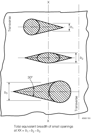
Figure 6.1.2 Isolated openings
1.6 Approved calculation systems
1.6.1 Where the
assumptions, method and procedures of a longitudinal strength calculation
system have received general approval from LR, calculations using
the system for a particular ship may be submitted.
1.7 Information required
1.7.1 In order
that an assessment of the longitudinal strength requirements can be
made, the following information is to be submitted, in LR's standard
format where appropriate:
-
General arrangement
and capacity plan or list, showing details of the volume and position
of centre of gravity of all tanks and compartments.
-
Details of the calculated
lightweight and its distribution.
-
Details of the weights, fore and aft extents, and centres of gravity
of all deadweight items for each of the main loading conditions. It is recommended
that this information be submitted in the form of a preliminary Loading
Manual.
-
Still water bending moments and shear forces for each of the main loading
conditions. It is recommended that in the preliminary Loading Manual, a suitable
margin be applied to the still water bending moments and shear forces to allow for
changes between the preliminary and final loading manuals. The responsibility for
the correctness of the submitted still water bending moments and shear forces
rests with the designer.
1.8 Loading guidance information
1.8.1 Sufficient
information is to be supplied to the Master of every craft to enable
him to arrange loading in such a way as to avoid the creation of unacceptable
stresses in the craft's structure.
|