
Section
4 Shell envelope framing
4.1 General
4.1.1 Except
as otherwise specified within this Section, the scantlings and arrangements
for shell envelope framing are to be determined in accordance with
the procedures described in, or as required by Pt 8, Ch 3, 4 Shell envelope framing for mono-hull craft, using the pressures from Pt 5 Design and Load Criteria appropriate to multi-hull craft.
4.1.2 The requirements
in this Section apply to longitudinally and transversely framed shell
envelopes.
4.2 Bottom outboard longitudinal stiffeners
4.2.1 The bottom
outboard longitudinal stiffeners are to be supported by bottom transverse
web frames, floors, bulkheads, or other primary structure, generally
spaced not more than 2 m apart.
4.2.2 Bottom
outboard longitudinal stiffeners are to be continuous through the
supporting structures.
4.2.3 Where it
is impracticable to comply with the requirements of Pt 8, Ch 4, 4.2 Bottom outboard longitudinal stiffeners 4.2.2, or where it is desired to terminate
the bottom outboard longitudinal stiffeners in way of the transom,
bulkheads or integral tank boundaries, they are to be bracketed in
way of their end connections to maintain the continuity of structural
strength. Particular care is to be taken to ensure accurate alignment
of the brackets.
4.2.4 The Rule
requirements for bending moment, shear force, shear stress and deflection
are to be determined from the general equations given in Pt 8, Ch 3, 1.15 Stiffeners general, using the design pressure
from Pt 5, Ch 3, 3.1 Hull structures or Pt 5, Ch 4, 3.1 Hull structures for non-displacement or
displacement type craft as appropriate, and the coefficients ΦM, ΦS and Φδ as indicated in Table 3.1.10 Shear force, bending moment and
deflection coefficients in Chapter 3 for the
load model (b).
4.3 Bottom outboard longitudinal primary stiffeners
4.3.1 The bottom
outboard longitudinal primary stiffeners are to be supported by bottom
transverse web frames, floors, bulkheads, or other primary structure,
generally spaced not more than 6 m apart.
4.3.2 Bottom
outboard longitudinal primary stiffeners are to be continuous through
the supporting structures.
4.3.3 Where it
is impracticable to comply with the requirements of Pt 8, Ch 4, 4.3 Bottom outboard longitudinal primary stiffeners 4.3.2, or where it is desired to terminate
the bottom outboard longitudinal primary stiffeners in way of the
transom, bulkheads or integral tank boundaries, they are to be bracketed
in way of their end connections to maintain the continuity of structural
strength. Particular care is to be taken to ensure accurate alignment
of the brackets.
4.3.4 The Rule
requirements for bending moment, shear force, shear stress and deflection
are to be determined from the general equations given in Pt 8, Ch 3, 1.15 Stiffeners general, using the design pressure
from Pt 5, Ch 3, 3.1 Hull structures or Pt 5, Ch 4, 3.1 Hull structures for non-displacement or
displacement type craft as appropriate, and the coefficients ΦM, ΦS and Φδ as indicated in Table 3.1.10 Shear force, bending moment and
deflection coefficients in Chapter 3 for the
load model (a).
4.4 Bottom outboard transverse stiffeners
4.4.1 Bottom
outboard transverse stiffeners are defined as local stiffening members
which support the bottom shell, and which may be continuous or intercostal.
4.4.2 The Rule
requirements for bending moment, shear force, shear stress and deflection
are to be determined from the general equations given in Pt 8, Ch 3, 1.15 Stiffeners general, using the design pressure
from Pt 5, Ch 3, 3.1 Hull structures or Pt 5, Ch 4, 3.1 Hull structures for high speed or displacement
type craft as appropriate, and the coefficients ΦM, ΦS and Φδ as indicated in Table 3.1.10 Shear force, bending moment and
deflection coefficients in Chapter 3 for the
load model (b).
4.5 Bottom outboard transverse frames
4.5.1 Bottom
outboard transverse frames are defined as stiffening members which
support the bottom shell. They are to be effectively continuous and
be bracketed at their end connections to side frames and bottom floors
as appropriate.
4.5.2 The Rule
requirements for bending moment, shear force, shear stress and deflection
are to be determined from the general equations given in Pt 8, Ch 3, 1.15 Stiffeners general, using the design pressure
from Pt 5, Ch 3, 3.1 Hull structures or Pt 5, Ch 4, 3.1 Hull structures for non-displacement or
displacement type craft as appropriate, and the coefficients ΦM, ΦS and Φδ as indicated in Table 3.1.10 Shear force, bending moment and
deflection coefficients in Chapter 3 for the
load model (a).
4.6 Bottom outboard transverse web frames
4.6.1 Bottom
outboard transverse web frames are defined as primary stiffening members
which support bottom shell longitudinals. They are to be continuous
and be substantially bracketed at their end connections to side web
frames and bottom floors.
4.6.2 Where it
is impracticable to comply with the requirements of Pt 8, Ch 4, 4.6 Bottom outboard transverse web frames 4.6.1, or where it is desired to terminate
the bottom inboard transverse web frames in way of bulkheads or integral
tank boundaries, etc. all web frames are to be bracketed in way of
their end connections, to maintain the continuity of structural strength.
Particular care is to be taken to ensure accurate alignment of the
brackets. All brackets are to be `soft toed' (see
Figure 3.4.1 `Soft-toe' in Chapter 3) and are to
terminate on suitable supporting structure capable of carrying the
transmitted bending moment.
4.6.3 The Rule
requirements for the bending moment, shear force, shear stress and
deflection are to be determined from the general equations given in Pt 8, Ch 3, 1.15 Stiffeners general, using the design pressure
from Pt 5, Ch 3, 3.1 Hull structures or Pt 5, Ch 4, 3.1 Hull structures for non-displacement or
displacement type craft as appropriate, and the coefficients ΦM, ΦS and Φδ as indicated in Table 3.1.10 Shear force, bending moment and
deflection coefficients in Chapter 3 for the
load model (a).
4.7 Bottom inboard longitudinal stiffeners
4.8 Bottom inboard longitudinal primary stiffeners
4.9 Bottom inboard transverse stiffeners
4.10 Bottom inboard transverse frames
4.11 Bottom inboard transverse web frames
4.12 Side outboard longitudinal stiffeners
4.12.1 The side
outboard longitudinal stiffeners are to be supported by side transverse
web frames, bulkheads, or other primary structure, generally spaced
not more than 2 m apart.
4.12.2 Side
outboard longitudinal stiffeners are to be continuous through the
supporting structures.
4.12.3 Where
it is impracticable to comply with the requirements of Pt 8, Ch 4, 4.12 Side outboard longitudinal stiffeners 4.12.2, or where it is desired to
terminate the side outboard longitudinal stiffeners in way of the
transom, bulkheads or integral tank boundaries, they are to be bracketed
in way of their end connections to maintain the continuity of structural
strength. Particular care is to be taken to ensure accurate alignment
of the brackets.
4.12.4 The Rule
requirements for the bending moment, shear force, shear stress and
deflection are to be determined from the general equations given in Pt 8, Ch 3, 1.15 Stiffeners general, using the design pressure
from Pt 5, Ch 3, 3.1 Hull structures or Pt 5, Ch 4, 3.1 Hull structures for non-displacement or
displacement type craft as appropriate, and the coefficients ΦM, ΦS and Φδ as indicated in Table 3.1.10 Shear force, bending moment and
deflection coefficients in Chapter 3 for the
load model (b).
4.13 Side outboard longitudinal primary stiffeners
4.13.1 The side
outboard longitudinal primary stiffeners are to be supported by side
transverse web frames, bulkheads, or other primary structure, generally
spaced not more than 6 m apart.
4.13.2 Side
outboard longitudinal primary stiffeners are to be continuous through
the supporting structures.
4.13.3 Where
it is impracticable to comply with the requirements of Pt 8, Ch 4, 4.13 Side outboard longitudinal primary stiffeners 4.13.2, or where it is desired to
terminate the side outboard longitudinal primary stiffeners in way
of the transom, bulkheads or integral tank boundaries, they are to
be bracketed in way of their end connections to maintain the continuity
of structural strength. Particular care is to be taken to ensure accurate
alignment of the brackets.
4.13.4 The Rule
requirements for bending moment, shear force, shear stress and deflection
are to be determined from the general equations given in Pt 8, Ch 3, 1.15 Stiffeners general, using the design pressure
from Pt 5, Ch 3, 3.1 Hull structures or Pt 5, Ch 4, 3.1 Hull structures for non-displacement or
displacement type craft as appropriate, and the coefficients ΦM, ΦS and Φδ as indicated in Table 3.1.10 Shear force, bending moment and
deflection coefficients in Chapter 3 for the
load model (a).
4.14 Side outboard transverse stiffeners
4.14.1 Side
outboard transverse stiffeners are defined as local stiffening members
which support the side shell, and which may be continuous or intercostal.
4.14.2 The Rule
requirements for bending moment, shear force, shear stress and deflection
are to be determined from the general equations given in Pt 8, Ch 3, 1.15 Stiffeners general, using the design pressure
from Pt 5, Ch 3, 3.1 Hull structures or Pt 5, Ch 4, 3.1 Hull structures for non-displacement or
displacement type craft as appropriate, and the coefficients ΦM, ΦS and Φδ as indicated in Table 3.1.10 Shear force, bending moment and
deflection coefficients in Chapter 3 for the
load model (b).
4.15 Side outboard transverse frames
4.15.1 Side
outboard transverse frames are defined as stiffening members supporting
the side shell and spanning continuously between bottom floors/frames
and decks. They are to be effectively constrained against rotation
at their end connections.
4.15.2 The Rule
requirements for bending moment, shear force, shear stress and deflection
are to be determined from the general equations given in Pt 8, Ch 3, 1.15 Stiffeners general, using the design pressure
from Pt 5, Ch 3, 3.1 Hull structures or Pt 5, Ch 4, 3.1 Hull structures for non-displacement or
displacement type craft as appropriate, and the coefficients ΦM, ΦS and Φδ as indicated in Table 3.1.10 Shear force, bending moment and
deflection coefficients in Chapter 3 for the
load model (a).
4.16 Side outboard transverse web frames
4.16.1 Side
outboard transverse web frames are defined as primary stiffening members
which support side shell longitudinals, they are to be continuous
and be substantially bracketed at their end connections to side web
frames and side floors.
4.16.2 Where
it is impracticable to comply with the requirements of Pt 8, Ch 4, 4.16 Side outboard transverse web frames 4.16.1, or where it is desired to
terminate the side outboard transverse web frames in way of bulkheads
or integral tank boundaries, etc. all web frames are to be bracketed
in way of their end connections, to maintain the continuity of structural
strength. Particular care is to be taken to ensure accurate alignment
of the brackets. All brackets are to be `soft toed' see
Figure 3.4.1 `Soft-toe' in Chapter 3, and are to
terminate on suitable supporting structure capable of carrying the
transmitted bending moment.
4.16.3 The Rule
requirements for bending moment, shear force, shear stress and deflection
are to be determined from the general equations given in Pt 8, Ch 3, 1.15 Stiffeners general, using the design pressure
from Pt 5, Ch 3, 3.1 Hull structures or Pt 5, Ch 4, 3.1 Hull structures for non-displacement or
displacement type craft as appropriate, and the coefficients ΦM, ΦS and Φδ as indicated in Table 3.1.10 Shear force, bending moment and
deflection coefficients in Chapter 3 for the
load model (a).
4.17 Side inboard longitudinal stiffeners
4.18 Side inboard longitudinal primary stiffeners
4.19 Side inboard transverse stiffeners
4.20 Side inboard transverse frames
4.21 Side inboard transverse web frames
4.22 Wet-deck longitudinal stiffeners
4.22.1 The wet-deck
longitudinal stiffeners are to be supported by transverse web frames,
bulkheads, or other primary structure, generally spaced not more than
2 m apart.
4.22.2 Wet-deck
longitudinal stiffeners are to be continuous through the supporting
structures.
4.22.3 Where
it is impracticable to comply with the requirements of Pt 8, Ch 4, 4.22 Wet-deck longitudinal stiffeners 4.22.2, or where it is desired to
terminate the wet-deck longitudinal stiffeners in way of the transom,
bulkheads or integral tank boundaries, they are to be bracketed in
way of their end connections to maintain the continuity of structural
strength. Particular care is to be taken to ensure accurate alignment
of the brackets.
4.22.4 The Rule
requirements for bending moment, shear force, shear stress and deflection
are to be determined from the general equations given in Pt 8, Ch 3, 1.15 Stiffeners general, using the design pressure
from Pt 5, Ch 3, 3.1 Hull structures or Pt 5, Ch 4, 3.1 Hull structures for non-displacement or
displacement type craft as appropriate, and the coefficients ΦM, ΦS and Φδ as indicated in Table 3.1.10 Shear force, bending moment and
deflection coefficients in Chapter 3 for the
load model (b).
4.23 Wet-deck longitudinal primary stiffeners
4.23.1 The wet-deck
longitudinal primary stiffeners are to be supported by transverse
web frames, bulkheads, or other primary structure, generally spaced
not more than 6 m apart.
4.23.2 Wet-deck
longitudinal primary stiffeners are to be continuous through the supporting
structures.
4.23.3 Where
it is impracticable to comply with the requirements of Pt 8, Ch 4, 4.23 Wet-deck longitudinal primary stiffeners 4.23.2, or where it is desired to
terminate the wet-deck longitudinal primary stiffeners in way of the
transom, bulkheads or integral tank boundaries, they are to be bracketed
in way of their end connections to maintain the continuity of structural
strength. Particular care is to be taken to ensure accurate alignment
of the brackets.
4.23.4 The Rule
requirements for bending moment, shear force, shear stress and deflection
are to be determined from the general equations given in Pt 8, Ch 3, 1.15 Stiffeners general, using the design pressure
from Pt 5, Ch 3, 3.1 Hull structures or Pt 5, Ch 4, 3.1 Hull structures for non-displacement or
displacement type craft as appropriate, and the coefficients ΦM, ΦS and Φδ as indicated in Table 3.1.10 Shear force, bending moment and
deflection coefficients in Chapter 3 for the
load model (a).
4.24 Wet-deck transverse stiffeners
4.24.1 Wet-deck
transverse stiffeners are defined as local stiffening members which
support the wet-deck shell, and which may be continuous or intercostal.
4.24.2 The Rule
requirements for bending moment, shear force, shear stress and deflection
are to be determined from the general equations given in Pt 8, Ch 3, 1.15 Stiffeners general, using the design pressure
from Pt 5, Ch 3, 3.1 Hull structures or Pt 5, Ch 4, 3.1 Hull structures for non-displacement or
displacement type craft as appropriate, and the coefficients ΦM, ΦS and Φδ as indicated in Table 3.1.10 Shear force, bending moment and
deflection coefficients in Chapter 3 for the
load model (b).
4.25 Wet-deck transverse frames
4.25.1 Wet-deck
transverse frames are defined as stiffening members which support
the wet-deck shell, they are to be effectively continuous and be bracketed
at their end connections to side frames and side floors as appropriate.
4.25.2 The Rule
requirements for bending moment, shear force, shear stress and deflection
are to be determined from the general equations given in Pt 8, Ch 3, 1.15 Stiffeners general, using the design pressure
from Pt 5, Ch 3, 3.1 Hull structures or Pt 5, Ch 4, 3.1 Hull structures for non-displacement or
displacement type craft as appropriate, and the coefficients ΦM, ΦS and Φδ as indicated in Table 3.1.10 Shear force, bending moment and
deflection coefficients in Chapter 3 for the
load model (a).
4.26 Wet-deck transverse web frames
4.26.1 Wet-deck
transverse web frames are defined as primary stiffening members which
support wet-deck longitudinals. They are to be continuous and be substantially
bracketed at their end connections to side web frames and side floors.
4.26.2 Where
it is impracticable to comply with the requirements of Pt 8, Ch 4, 4.26 Wet-deck transverse web frames 4.26.1, or where it is desired to
terminate the wet-deck transverse web frames in way of bulkheads or
integral tank boundaries, etc. all web frames are to be bracketed
in way of their end connections, to maintain the continuity of structural
strength. Particular care is to be taken to ensure accurate alignment
of the brackets. All brackets are to be 'soft toed', see
Figure 3.4.1 `Soft-toe' in Chapter 3, and are to
terminate on suitable supporting structure capable of carrying the
transmitted bending moment.
4.26.3 The Rule
requirements for bending moment, shear force, shear stress and deflection
are to be determined from the general equations given in Pt 8, Ch 3, 1.15 Stiffeners general, using the design pressure
from Pt 5, Ch 3, 3.1 Hull structures or Pt 5, Ch 4, 3.1 Hull structures for non-displacement or
displacement type craft as appropriate, and the coefficients ΦM, ΦS and Φδ as indicated in Table 3.1.10 Shear force, bending moment and
deflection coefficients in Chapter 3 for the
load model (a).
4.26.6 Primary
transverse web frame members which link the strength deck to the wet-deck
structure and which carry the transverse global loading, are additionally
to comply with Pt 8, Ch 6, 3.4 Torsional strength.
4.26.7 Particular
care is to be taken to ensure that the continuity of transverse structural
strength is maintained. All primary transverse members are to be continuous
through the side inboard structure and be integrated into transverse
bulkheads or other primary structure within each hull, see
Figure 4.4.1 End connection detail, wet-deck structure. In the case of trimaran
type craft the primary transverse members are to be continuous through
the centre hull. Additionally the side inboard shell laminate in way
of the intersection is to be locally increased in thickness by not
less than 50 per cent. Copies of direct calculations are to be submitted
for consideration.
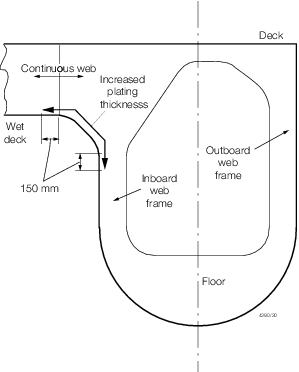
Figure 4.4.1 End connection detail, wet-deck structure
4.27 Novel features
4.27.1 Where
the Rules do not specifically define the requirements for novel features
then the scantlings and arrangements are to be determined by direct
calculations. Such calculations are to be carried out on the basis
of the Rules, recognised standards and good practice, and are to be
submitted for consideration.
|