
Section
3 Vehicle decks
3.1 General
3.1.1 These requirements
are applicable to longitudinally or transversely framed craft intended
for the carriage of wheeled vehicles, or where wheeled vehicles are
to be used for cargo handling.
3.1.2 The deck
and supporting structure are to be designed on the basis of the maximum
loading to which they may be subjected in service. Where applicable,
the hatch covers are to be similarly designed. In no case, however,
are the scantlings to be less than would be required for a weather
or cargo deck, or hatch cover, as applicable.
3.1.3 Details
of the deck loading resulting from the proposed stowage or operation
of vehicles are to be supplied by the Builder. These details are to
include axle and wheel spacing, the wheel load, type of tyre and tyre
print dimensions for the vehicles. The vehicle types and wheel loads
for which the vehicle decks, including hatch covers where applicable,
have been approved are to be included in the craft's documentation
and contained in a notice displayed on each deck. For design purposes,
the wheel loading is to be taken as not less than 3,0 kN.
3.1.4 The scantling
requirements are based on structural strength and limitations on stress
and deflection, with no allowance made for wear and tear. Local reinforcement
is to be fitted as necessary, particularly in way of vehicle lanes
and passenger routes.
3.1.5 The webs
of vehicle deck stiffening members are in no cases to be scalloped.
3.2 Definitions
3.2.1
Load
area. The load area is defined as the footprint area of an
individual wheel or the area enclosing a group of wheels when the
distance between footprints is less than the smaller dimension of
the individual prints.
3.3 Deck plating
3.3.1 The thickness, t
p, of vehicle deck plating is to be taken as not
less than:
s and k
a are as defined
in Pt 7, Ch 5, 1.2 Symbols and definitions.
Table 5.3.1 Deck plate thickness
calculation
| Symbols
|
Expression
|
|
a, s, u, and v as defined in Figure 5.3.1 Tyre print chart
n= tyre correction factor as detailed in Table 5.3.2 Tyre correction factor, n
P1 = corrected patch load, in tonnes
λ = dynamic magnification factor
Pw = load, in tonnes, on the tyre print.
For closely spaced wheels the shaded area shown in Figure 5.3.1 Tyre print chart may be taken as the combined
print
λ = dynamic magnification factor
φ1 = patch aspect ratio correction
factor
φ2 = panel aspect ratio correction
factor
φ3 = wide patch load factor
|
|
|
|
v
1 = v, but ≤ s
|
| u
1 = u, but ≤ a
|
|
|
u ≤ (a -
s)
|

|
for a ≥
u > (a - s)
|
|
|
for u >
a
|

|
for v <
s
|

|
for 1,5 >
(v/s) > 1,0
|

|
for (v/s) ≥
1,5
|
|
λ |
= |
1,25 for craft operating in G1 |
|
|
= |
(1 + 0,35n) for craft operating in G2 |
|
|
= |
(1 + 0,385n) for craft operating in G2A |
|
|
= |
(1 + 0,42n) for craft operating in G3 |
|
|
= |
(1 + 0,49n) for craft operating in G4 |
|
|
= |
(1 + 0,56n) for craft operating in G5 |
|
|
= |
(1 + 0,70n) for craft operating in G6 |
|
| G1, G2, G2A,
G3, G4, G5 and G6 as defined in Pt 1, Ch 2, 3.5 Service area restriction notations 3.5.5
|
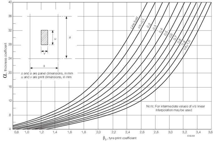
Figure 5.3.1 Tyre print chart
3.4 Secondary stiffening
3.4.1 The scantlings
of vehicle deck stiffeners are to be as required to satisfy the most
severe arrangement of print wheel loads in conjunction with the cargo/weather
deck design head.
3.4.2 The minimum
requirements for section modulus, inertia and web area of vehicle
deck secondary stiffeners subject to wheel loading are to be calculated
in accordance with Table 5.3.3 Secondary stiffener
requirements, see also
Figure 5.3.1 Tyre print chart and Table 5.3.2 Tyre correction factor, n.
Table 5.3.2 Tyre correction factor, n
| Number of wheels in
idealised patch
|
Pneumatic tyres
correction factor, n
|
Solid rubber tyres
correction factor, n
|
| 1
|
0,6
|
0,8
|
| 2 or more
|
0,75
|
0,9
|
Table 5.3.3 Secondary stiffener
requirements
| Scantling
requirement
|
Load case
|
d ≤ 
|
d > 
|
| Section modulus (Z)
(cm3)
|
|
|
Inertia  (cm4) (cm4)
|
|
|
| Web area (A
w) (cm2)
|
|
|
| Symbols
|
|
P
|
= |
maximum effective load per wheel or group of wheels,
in kN |
|

|
= |
overall secondary stiffener length, in metres |
|
|
s
|
= |
stiffener spacing, in metres |
|
|
d
|
= |
dimension of load area parallel to stiffener axis, in
metres |
|
|
E
|
= |
Young's modulus of elasticity of material, in
N/mm2
|
|
|
w
|
= |
dimension of load area perpendicular to stiffener
axis, in metres |
|
|
k
w
|
= |
lateral loading factor |
| = |
|
|
|
|
|
|
|
|
|
|
|
|
|
σ
a
|
= |
0,2% proof stress of material, in N/mm2
|
|

|
= |
shear stress of the alloy, in N/mm2
|
| = |

|
|
Note
Z
dk,  , A
dk , A
dk
|
= |
For vehicle decks, stiffener requirements to be
determined in accordance with Pt 7, Ch 3, 8.7 Strength/weather deck stiffening and Pt 7, Ch 3, 8.10 Cargo deck stiffening using the appropriate design
pressures, but not to be taken as less than 2kN/m2. |
| = |
For helicopter decks, stiffener requirements to
be determined in accordance with Pt 7, Ch 3, 8.7 Strength/weather deck stiffening using the uniformly
distributed loads given in Table 5.6.2 Design load cases for deck
stiffening and supporting structure.
|
|
3.4.3 When two
or more load areas are located simultaneously on the same stiffener
span, the scantling requirements are to be specially considered on
the basis of direct calculation.
3.5 Primary stiffening
3.5.1 The scantlings
of vehicle deck primary girders and transverse web frames are to be
determined on the basis of direct calculation in association with
the limiting permissible stress and deflection criteria contained
in Pt 7, Ch 7 Failure Modes Control.
3.6 Securing arrangements
3.6.1 Details
of the connections to the hull of vehicle securing arrangements are
to be submitted for approval.
3.6.2 Deck fittings
in way of vehicle lanes are to be recessed.
3.6.3 The vehicle
deck structure is to be of adequate strength for the upward forces
imposed at fixed securing points. Local reinforcement is to be fitted
as necessary.
3.7 Access
3.7.3 Doors providing
pedestrian access between vehicle decks and accommodation spaces are
to be gastight, have scantlings equivalent to the surrounding structure
and where applicable are to comply with the requirements of Pt 17 Fire Protection, Detection and Extinction.
3.8 Hatch covers
3.8.1 The scantlings
and arrangements of hatches and hatch covers located within vehicle
decks are to be not less than that required by the Rules for the supporting
structure in which such hatches are fitted. In general the end fixity
of primary stiffening members is to be taken as simply supported.
Local and secondary stiffening members may be either partially or
fully fixed at their end connections dependent upon the proposed arrangement.
3.8.2 In no case,
however, are the scantlings of plating and stiffeners to be less than
would be required for a weather or cargo deck, or hatch cover, as
applicable.
3.8.3 Where unusual
arrangements of hatch cover stiffening are proposed, the scantlings
of plating and stiffeners may be determined by direct calculations
using a two-dimensional grillage model. A copy of the calculations
is to be submitted.
3.9 Heavy and special loads
3.9.1 Where heavy
or special loads are proposed to be carried, the scantlings and arrangements
of the deck structure will be individually considered on the basis
of submitted calculations.
3.9.2 Due account
is to be taken of the acceleration levels due to craft motion as applicable
to particular items of heavy mass such as vehicles, containers, pallets,
etc.
3.10 Direct calculations
3.10.1 LR will
consider direct calculations for the derivation of scantlings as an
alternative to and equivalent to those derived by Rule requirements.
The assumptions made and the calculation procedures used are to be
submitted for appraisal in accordance with Pt 3, Ch 1, 2 Direct calculations.
|