
Section
4 Bow doors
4.1 Application
4.1.1 The requirements
of this Section are applicable to the arrangement, strength and securing
of bow doors, both the visor and the side opening type doors, and
inner doors leading to a complete or long forward enclosed superstructure.
4.1.2 Other types
of bow door will be specially considered.
4.2 General
4.2.1 The attention
of Owners and Builders is drawn to the additional statutory regulations
for bow doors that may be imposed by the National Authority.
4.2.2 Bow doors
are to be situated above the freeboard deck. A watertight recess in
the freeboard deck located forward of the collision bulkhead and above
the deepest waterline fitted for arrangement of ramps or other related
mechanical devices may be regarded as a part of the freeboard deck.
4.2.3 An inner
door is to be fitted. The inner door is to be part of the collision
bulkhead. The inner door need not be fitted directly above the bulkhead
below, provided it is located within the limits specified for the
position of the collision bulkhead, see
Pt 3, Ch 2, 4 Bulkhead arrangements. A vehicle ramp may be arranged
for this purpose, provided its position complies with Pt 3, Ch 2, 4 Bulkhead arrangements and the ramp is weathertight
over its complete length. In this case the upper part of the ramp
higher than 2,3 m above the freeboard deck may extend forward of the
limit specified in Pt 3, Ch 2, 4 Bulkhead arrangements.
If this is not possible a separate inner weathertight door is to be
installed, as far as practicable within the limits specified for the
position of the collision bulkhead.
4.2.4 Bow doors
are to be fitted as to ensure tightness consistent with operational
conditions and to give effective protection to inner doors. Inner
doors forming part of the collision bulkhead are to be weathertight
over the full height of the cargo space and arranged with fixed sealing
supports on the aft side of the doors.
4.2.5 Bow doors
and inner doors are to be arranged so as to preclude the possibility
of the bow door causing structural damage to the inner door or to
the collision bulkhead in the case of damage to or detachment of the
bow door. If this is not possible, a separate inner weathertight door
is to be installed, as indicated in Pt 7, Ch 5, 4.2 General 4.2.3.
4.2.6 The requirements
for inner doors are based on the assumption that vehicles are effectively
lashed and secured against movement in the stowed position.
4.3 Symbols and definitions
4.3.1 The symbols
used in this Section are defined as follows:
|
A
s
|
= |
area stiffener web in cm2
|
|
A
x
|
= |
area, in m2, of the transverse vertical projection
of the door between the levels of the bottom of the door and the upper
deck or between the bottom of the door and the top of the door, whichever
is the lesser, as shown in Figure 5.4.2 Bow visor (upward hinging)
|
|
A
y
|
= |
area, in m2, of the longitudinal vertical projection
of the door between the levels of the bottom of the door and the upper
deck or between the bottom of the door and the top of the door, whichever
is the lesser
|
|
A
z
|
= |
area of the horizontal projection of the door between the levels
of the bottom of the door and the upper deck or between the bottom
of the door and the top of the door, in m2, whichever is
the lesser, as shown in Figure 5.4.2 Bow visor (upward hinging)
|
|
h
|
= |
height
of the door between the levels of the bottom of the door and the upper
deck or between the bottom of the door and the top of the door, in
metres, whichever is the lesser, as shown in Figure 5.4.1 Measurement of αf and βe
|
|
W
bv
|
= |
mass of the visor door, in tonnes |
|
τ |
= |
shear stress,
in N/mm2
|
|
σ |
= |
bending
stress, in N/mm2
|
|
σa
|
= |
material
yield stress, in N/mm2
|
|
σeq
|
= |
equivalent
stress, in N/mm2
|
|
|
= |
 . .
|
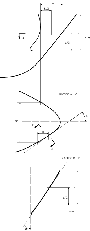
Figure 5.4.1 Measurement of αf and βe
4.3.2
Locking
device. A device that locks a securing device in the closed
position.
4.3.3
Securing
device. A device used to keep the door closed by preventing
it from rotating about its hinges.
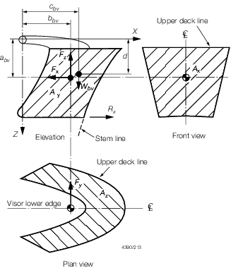
Figure 5.4.2 Bow visor (upward hinging)
4.3.4
Side-opening
doors. Side-opening doors are opened either by rotating outwards
about a vertical axis through two or more hinges located near the
outboard edges or by horizontal translation by means of linking arms
arranged with pivoted attachments to the door and the craft. It is
anticipated that side-opening doors are arranged in pairs.
4.3.5
Supporting
device. A device used to transmit external or internal loads
from the door to a securing device and from the securing device to
the craft's structure, or a device other than a securing device, such
as a hinge, stopper or other fixed device, that transmits loads from
the door to the craft's structure.
4.3.6
Visor
doors. Visor doors are opened by rotating upwards and outwards
about a horizontal axis through two or more hinges located near the
top of the door and connected to the primary structure of the door
by longitudinally arranged lifting arms.
4.4 Strength criteria
4.4.1 Scantlings
of the primary members, securing and supporting devices of bow doors
and inner doors are to be able to withstand the design loads defined
in Pt 7, Ch 5, 4.5 Design loads. The shear, bending and
equivalent stresses are not to exceed 43/k
a N/mm2, 64/k
a N/mm2 and 80/k
a N/mm2 respectively.
4.4.3 For metal
to metal bearings in securing and supporting devices, the nominal
bearing pressure calculated by dividing the design force by the projected
bearing area is not to exceed 80 per cent of the yield stress of the
bearing material. For other bearing materials, the permissible bearing
pressure is to be determined according to the manufacturer's specification.
4.4.4 The arrangement
of securing and supporting devices is to be such that threaded bolts
do not carry support forces. The maximum tension in way of threads
of steel bolts not carrying support forces is not to exceed 125/k
s N/mm2.
4.5 Design loads
4.5.1 The design
external pressure, P
e, for the determination
of scantlings for primary members, securing and supporting devices
of bow doors is taken to be not less than the following:

where
|
V
max
|
= |
maximum speed in knots as defined in Pt 1, Ch 2, 2.2 Definitions 2.2.11.
|
|
L
R
|
= |
Rule length of craft, in m as defined in Pt 3, Ch 1, 6 Definitions
|
|
λ
G
|
= |
Service group factor for mono-hull craft, see
Pt 1, Ch 2 Classification Regulations
|
|
|
= |
0,5 for Group 1
and 2 |
|
|
= |
0,6 for Group 3 |
|
|
= |
0,8 for Group 4 |
|
|
= |
1,0 for Groups
5 and 6 |
|
|
= |
For multi-hull craft, λG will be specially considered and may be reduced where the
freeboard is significant
|
|
C
H
|
= |
0,0125L
R for L
R <
80 m
|
|
|
= |
1,0 for L
R ≥ 80 m
|
|
α
f
|
= |
flare angle at the point to be considered, defined as the angle
between a vertical line and the tangent to the side shell plating,
measured in a vertical plane normal to the horizontal tangent to the
shell plating, see
Figure 5.4.1 Measurement of αf and βe
|
|
β
e
|
= |
entry angle at the point to be considered, defined as the angle
between a longitudinal line parallel to the centreline and the tangent
to the shell plating in a horizontal plane, see
Figure 5.4.1 Measurement of αf and βe
|
4.5.2 The design
external forces, F
x, F
y and F
z, in kN, for the determination of scantlings of
securing and supporting devices of bow doors are taken to be not less
than P
e
A
x, P
e
A
y and P
e
A
z respectively. Where P
e is the external
pressure, defined in Pt 7, Ch 5, 4.5 Design loads 4.5.1, with
the flare angle, αf, and the entry angle, βe,
measured at the point on the bow door,  d/2 aft of the stem line on the plane h/2
above the bottom of the door, as shown in Figure 5.4.1 Measurement of αf and βe
. A
x, A
y, A
z and h as defined in Pt 7, Ch 5, 4.3 Symbols and definitions 4.3.1.
d/2 aft of the stem line on the plane h/2
above the bottom of the door, as shown in Figure 5.4.1 Measurement of αf and βe
. A
x, A
y, A
z and h as defined in Pt 7, Ch 5, 4.3 Symbols and definitions 4.3.1.
4.5.3 For bow
doors, including bulwark, of unusual form or proportions, the areas
used for the determination of the design values of external forces
will be specially considered.
4.5.5 The lifting
arms of a visor and its supports are to be dimensioned for the static
and dynamic forces applied during the lifting and lowering operations,
and a minimum wind pressure of 1,5kN/m2 is to be taken.
4.5.6 The design
external pressure, in kN/m2, for the determination of scantlings
for primary members, securing and supporting devices and surrounding
structure of inner doors is to be taken as the greater of 0,45L
R and 10h
2, where h
2 is
the distance, in m, from the load point to the top of the cargo space
and L
R as defined in Pt 3, Ch 1, 6.2 Principal particulars 6.2.1.
4.5.7 The design
internal pressure for the determination of scantlings for securing
devices of inner doors is not to be taken less than 25 kN/m2.
4.6 Scantlings of bow doors
4.6.1 The strength
of bow doors is to be commensurate with that of the surrounding structure.
4.6.2 Bow doors
are to be adequately stiffened and means are to be provided to prevent
lateral or vertical movement of the doors when closed. For visor doors
adequate strength for the opening and closing operations is to be
provided in the connections of the lifting arms to the door structure
and to the craft structure.
4.6.3 The thickness
of the bow plating is not to be less than that required for the side
shell plating, using bow door stiffener spacing, but in no case less
than the minimum required thickness of fore end shell plating.
4.6.4 The section
modulus of horizontal or vertical stiffeners is not to be less than
that required for end framing. Consideration is to be given, where
necessary, to differences in fixity between craft's frames and bow
doors stiffeners.
4.6.6 The bow
door secondary stiffeners are to be supported by primary members constituting
the main stiffening of the door.
4.6.7 The primary
members of the bow door and the hull structure in way are to have
sufficient stiffness to ensure integrity of the boundary support of
the door.
4.7 Scantlings of inner doors
4.7.1 Scantlings
of the primary members are generally to be supported by direct calculations
in association with the external pressure given in and permissible
stresses given in Pt 7, Ch 5, 4.4 Strength criteria 4.4.1. In general,
formulae for simple beam theory may be applied.
4.7.2 Where inner
doors also serve as a vehicle ramps, the scantlings are not to be
less than those required for vehicle decks.
4.7.3 The distribution
of the forces acting on the securing and supporting devices is, in
general, to be supported by direct calculations taking into account
the flexibility of the structure and actual position and stiffness
of the supports.
4.8 Securing and supporting of bow doors
4.8.1 Bow doors
are to be fitted with adequate means of securing and supporting so
as to be commensurate with the strength and stiffness of the surrounding
structure. The hull supporting structure in way of the bow doors is
to be suitable for the same design loads and design stresses as the
securing and supporting devices. Where packing is required, the packing
material is to be of a comparatively soft type, and the supporting
forces are to be carried by the steel structure only. Other types
of packing may be considered. Maximum design clearance between securing
and supporting devices is, in general, not to exceed 3 mm. A means
is to be provided for mechanically fixing the door in the open position.
4.8.2 Only the
active supporting and securing devices having an effective stiffness
in the relevant direction are to be included and considered to calculate
the reaction forces acting on the devices. Small and/or flexible devices
such as cleats intended to provide load compression of the packing
material are, in general, not to be included in the calculations called
for in Pt 7, Ch 5, 4.8 Securing and supporting of bow doors 4.8.8. The number of securing
and supporting devices are, in general, to be the minimum practical
whilst taking into account the requirements for redundant provision
given in Pt 7, Ch 5, 4.8 Securing and supporting of bow doors 4.8.9 and Pt 7, Ch 5, 4.8 Securing and supporting of bow doors 4.8.10 and the available space for
adequate support in the hull structure.
4.8.3 For opening
outwards visor doors, the pivot arrangement is generally to be such
that the visor is self closing under external loads, that is M
y > 0. Moreover, the closing moment, M
y,
as given in Pt 7, Ch 5, 4.5 Design loads 4.5.4 is to be not
less than:
where
W
bv, a
bv, b
bv and c
bv are
as defined in Pt 7, Ch 5, 4.3 Symbols and definitions 4.3.1
F
x and F
z as defined in Pt 7, Ch 5, 4.5 Design loads 4.5.2.
4.8.4 Securing
and supporting devices are to be adequately designed so that they
can withstand the reaction forces within the permissible stresses
given in Pt 7, Ch 5, 4.4 Strength criteria 4.4.1.
4.8.5 For visor
doors the reaction forces applied on the effective securing
and supporting devices assuming the door as a rigid body are determined
for the following combination of external loads acting simultaneously
together with the self weight of the door.
| Case 1
|
F
x and F
z.
|
| Case 2
|
0,7F
y acting on each side separately together with 0,7F
x and 0,7F
z.
|
where F
x, F
y and F
z are to be determined
as indicated in Pt 7, Ch 5, 4.5 Design loads 4.5.2 and applied
at the centroid of projected areas.
4.8.6 For side-opening
doors the reaction forces applied on the effective securing
and supporting devices assuming the door as a rigid body are determined
for the following combination of external loads acting simultaneously
together with the self weight of the door:
| Case 1
|
F
x, F
y and F
z acting on both doors.
|
| Case 2
|
0,7 F
x and 0,7F
z acting on both doors and 0,7F
y acting on each door separately.
|
where
F
x, F
y and F
z are to be determined
as indicated in Pt 7, Ch 5, 4.5 Design loads 4.5.2 and applied
at the centroid of projected areas.
4.8.8 The distribution
of the reaction forces acting on the securing and supporting devices
may require to be supported by direct calculations taking into account
the flexibility of the hull structure and the actual position and
stiffness of the supports.
4.8.9 The arrangement
of securing and supporting devices in way of these securing devices
is to be designed with redundancy so that in the event of failure
of any single securing or supporting device the remaining devices
are capable of withstanding the reaction forces without exceeding
by more than 20 per cent the permissible stresses as given in Pt 7, Ch 5, 4.4 Strength criteria 4.4.1.
4.8.10 For visor
doors, two securing devices are to be provided at the lower
part of the door, each capable of providing the full reaction force
required to prevent opening of the door within the permissible stresses
given in Pt 7, Ch 5, 4.4 Strength criteria 4.4.1. The opening moment, M
o, to be balanced by this reaction force, is not
to be taken less than:
where
W
bv, A
x, d
bv and a
bv are
as defined in Pt 7, Ch 5, 4.3 Symbols and definitions 4.3.1.
4.8.11 For visor
doors, the securing and supporting devices excluding the hinges
should be capable of resisting the vertical design force (F
z - 10W
bv), in kN, within the permissible
stresses given in Pt 7, Ch 5, 4.4 Strength criteria 4.4.1.
4.8.12 All load
transmitting elements in the design load path, from door through securing
and supporting devices into the craft structure, including welded
connections, are to be the same strength.
4.8.13 For side-opening
doors, thrust bearing has to be provided in way of girder ends
at the closing of the two leaves to prevent one leaf to shift towards
the other one under effect of unsymmetrical pressure, see
Figure 5.4.3 Typical thrust bearing. Each part of the thrust
bearing has to be kept secured on the other part by means of securing
devices. Any other arrangements serving the same purpose are to be
submitted for appraisal.
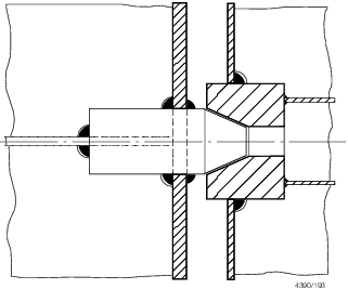
Figure 5.4.3 Typical thrust bearing
4.9 Securing and locking arrangement
4.9.1 Securing
devices are to be simple to operate and easily accessible. Securing
devices are to be equipped with mechanical locking arrangement (self
locking or separate arrangement), or be of the gravity type. The opening
and closing systems as well as securing and locking devices are to
be interlocked in such a way that they can only operate in the proper
sequence.
4.9.2 Bow doors
and inner doors giving access to vehicle decks are to be provided
with an arrangement for remote control, from a position above the
freeboard deck, of:
-
the closing and opening
of the doors, and
-
associated securing
and locking devices for every door.
Indication of the open/closed position of every door and every
securing and locking device is to be provided at the remote control
stations. The operating panels for operation of doors are to be inaccessible
to unauthorised persons. A notice plate, giving instructions to the
effect that all securing devices are to be closed and locked before
leaving harbour, is to be placed at each operating panel and is to
be supplemented by warning indicator lights.
4.9.3 Where hydraulic
securing devices are applied, the system is to be mechanically lockable
in the closed position so that in the event of loss of the hydraulic
fluid, the securing devices remain locked. The hydraulic system for
securing and locking devices is to be isolated from other hydraulic
circuits when in the closed position.
4.9.4 Separate
indicator lights and audible alarms are to be provided on the navigation
bridge and on the operating panel to show that the bow door and inner
door are closed and that their securing and locking devices are properly
positioned. The indication panel is to be provided with a lamp test
function. The indicator lights are to be provided with a permanent
power supply, further, arrangements are to be such that it is not
possible to turn off these lights in service.
4.9.5 The indicator
system is to be designed on the fail-safe principle and is to show
by visual alarms if the door is not fully closed and not fully locked
and by audible alarms if securing devices become open or locking devices
become unsecured. The power supply for the indicator system is to
be independent of the power supply for operating and closing the doors.
The sensors of the indicator system are to be protected from water,
ice formation and mechanical damages.
4.9.6 The indication
panel on the navigation bridge is to be equipped with a mode selection
function `harbour/sea voyage', so arranged that audible alarm is given
if the craft leaves harbour with the bow door or inner door not closed
and with any of the securing devices not in the correct position.
4.9.7 A water
leakage detection system with audible alarm and television surveillance
are to be arranged to provide an indication to the navigation bridge
and to the engine control room of leakage through the inner door.
4.9.8 Between
the bow door and the inner door a television surveillance system is
to be fitted with a monitor on the navigation bridge and in the engine
control room. The system is to be able to monitor the position of
doors and a sufficient number of their securing devices. Special consideration
is to be given for lighting and contrasting colour of objects under
surveillance.
4.9.9 A drainage
system is to be arranged in the area between bow door and ramp, as
well as in the area between the ramp and inner door where fitted.
The system is to be equipped with an audible alarm function to the
navigation bridge for water level in these areas exceeding 0,5 m above
the car deck level.
4.10 Operating and Maintenance Manual
4.10.1 An Operating
and Maintenance Manual for the bow door and inner door is to be provided
on board and contain necessary information on:
-
main particulars
and design drawings,
-
service conditions,
e.g. service area restrictions, acceptable clearances for supports,
-
maintenance and
function testing,
-
register of inspections
and repairs.
This manual is to be submitted for approval.
4.10.2 Documented
operating procedures for closing and securing the bow door and inner
door are to be kept on board and posted at an appropriate place.
|