
Section
2 Rudders
2.1 General
2.1.2 For rudders
having an increased diameter of rudder stock, see
Figure 3.2.1 Rudder types, the increased diameter
is to be maintained to a point as far as practicable above the top
of the lowest bearing. This diameter may then be tapered to the diameter
required in way of the tiller. The length of the taper is to be at
least three times the reduction in diameter. Particular care is to
be taken to avoid the formation of a notch at the upper end of the
taper.
2.1.3 Sudden
changes of section or sharp corners in way of the rudder coupling,
jumping collars and shoulders for rudder carriers, are to be avoided.
2.2 Definition and symbols
2.2.1 Definitions
and symbols for use throughout this Section are indicated in the appropriate
tables.
2.3 Direct calculations
2.3.1 Where the
rudder is of a novel design, high aspect ratio or the speed of the
craft exceeds 45 knots the scantlings of the rudder and rudder stock
are to be determined by direct calculation methods incorporating model
test results and structural analysis, where considered necessary by
LR.
2.4 Equivalents
2.4.1 Alternative
methods of determining the loads will be specially considered, provided
that they are based on model tests, full scale measurements or generally
accepted theories. In such cases, full details of the methods used
are to be provided when plans are submitted for approval.
2.5 Rudder arrangements
2.5.1 Rudders
considered are the types shown in Figure 3.2.1 Rudder types, of double plate or single plate construction, constructed
from steel, stainless steel or aluminium alloy. Other rudder types
and materials will be subject to special consideration.
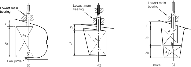
Figure 3.2.1 Rudder types
2.6 Rudder profile coefficient f
R
2.7 Rudder position coefficient f
p
2.8 Rudder speed coefficient f
v
2.9 Pintle arrangement coefficient N
2.9.1 The pintle
arrangement coefficient, N, for use in Table 3.2.6 Rudder stock diameter is to be as indicated in Table 3.2.4 Pintle arrangement coefficient
N
.
Table 3.2.5 Position of centre of
pressure
| Design criteria
|
Value of x
PF and x
PA to be used in Table 3.2.6 Rudder stock diameter
|
| Rectangular rudders;
|
|
|
|
| (a) Ahead condition
|
x
PF
|
=
|
(0,33ex
B-x
L), but not less than 0,12x
B
|
| (b) Astern condition
|
x
PA
|
=
|
(x
A- 0,25x
B), but not less than 0,12x
B
|
| Non-rectangular rudders;
|
|
| (a) Ahead condition
|
x
PF
|
=
|
as calculated from geometric form
(see Note) but not less than: 
|
| (b) Astern condition
|
x
PA
|
=
|
as calculated from geometric form
(see Note) but not less than: 
|
| Symbols
|
|
x
PF
|
= |
horizontal distance from the centreline of the rudder
pintles, or axle, to the centre of pressure in the ahead condition,
in metres |
|
|
x
PA
|
= |
horizontal distance from the centreline of the rudder
pintles, or axle, to the centre of pressure in the astern
condition, in metres |
|
|
x
B
|
= |
breadth of rudder, in metres |
|
|
y
R
|
= |
depth of rudder at centreline of stock, in metres |
|
|
|
|
x
L and x
A
|
= |
horizontal distances from leading and after edges,
respectively, of the rudder to the centreline of the rudder
pintles, or axle, in metres |
|
|
x
S
|
= |
horizontal length of any rectangular strip of rudder
geometric form, in metres |
|
|
e
|
= |
hull form factor at ahead condition |
|
| for
L < 65 m , e = 1,0
|
for
L ≥ 65 m, e= or or
|
e= 
|
| whichever is the lesser, but not less than 1,0 and need not be taken
greater than 1,5
|
| L
R, B and C
b are as defined Pt 3, Ch 1, 6.2 Principal particulars is as defined in Table 3.2.6 Rudder stock diameter
|
| NOTE
|
| For
rectangular strips the centre of pressure is to be assumed to be located as
follows:
|
| (a)
0,33ex
S abaft leading edge of strip for ahead condition.
|
| (b)
0,25x
S from aft edge of strip for astern condition.
|
2.10 Centre of pressure
2.11 Rudder stock (tubular)
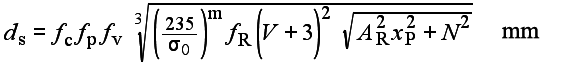
2.11.1 Tubular rudder stock scantlings are to be not
less than that necessary to provide the equivalent strength of a solid stock as required
by Table 3.2.6 Rudder stock diameter, and can be calculated from the following
formula:

where
|
d
E
|
= |
the diameter of the equivalent solid rudder stock, in mm |
|
d
1, d
2
|
= |
external and internal diameters, respectively of the tubular stock,
in mm |
Table 3.2.6 Rudder stock diameter
| Requirement
|
|
1. Basic stock diameter, d
s, at and below lowest bearing:
|
|
|
2. Diameter in way of tiller, d
SU:
|
d
SU
|
= |
d
s calculated from (1) with N=0 |
|
|
3. Lateral force on rudder acting at centre of pressure of
blade, P
L:
|
|
|
| Symbols
|
|
f
c
|
= |
79 for craft of Rule length, L
R, 50 m and below varying up to 83,3 at a Rule length,
L
R, of 70 m. Intermediate values to be obtained by
interpolation |
| = |
83,3 for craft of Rule length, L
R, 70 m and above |
|
|
|
|
|
|
|
|
m
|
= |
0,75 for σ0 > 235 |
| = |
1,0 for σ0 ≤ 235 |
|
|
σ0
|
= |
minimum yield stress, in N/mm2, of material
used, and is not to be taken greater than 0,7 σT
|
|
|
σT
|
= |
ultimate tensile strength of the material used, in
N/mm2
|
|
|
V
|
= |
the maximum speed for the astern and ahead condition,
in knots. In no case to be less than 5 knots |
|
|
|
|
|
|
|
Note Where higher tensile steel is used for the rudder stock,
σ0 is not to be taken as greater than 450
N/mm2.
|
2.12 Single plate rudders
2.12.2 Rudder
arms are to be efficiently attached to the mainpiece.
Table 3.2.7 Single plate rudder
construction
| Item
|
Requirement
|
| Blade thickness
|
t
B = 0,0015Vy
W + 2,5 mm with a minimum of 10 mm
|
| Arms
|
Spacing ≤ 1000mm
|
|
Z
A = 0,0005V
2
x
a
2
y
W cm3
|
| Mainpiece
|
Diameter = d
s mm
|
| For spade rudders, the lower third may
taper down to 0,75d
s mm
|
| Symbols
|
|
t
B
|
= |
blade thickness, in mm |
|
y
W
|
= |
vertical spacing of rudder arms, in mm |
|
x
a
|
= |
horizontal distance from the aft edge of the rudder
to the centre of the rudder stock, in metres |
|
z
A
|
= |
section modulus of arm, in cm3
|
|
2.13 Double plate rudders
2.13.2 In way
of rudder couplings and heel pintles the plating thickness is to be
suitably increased.
2.13.3 On semi-spade (Mariner) type rudders a notch effect in the corners in the
bottom pintle region is to be avoided (see AA, Figure 3.2.3 Semi-spade (mariner) type rudder). An insert plate, 1,6 times the Rule thickness
of the side plating, is to be fitted at this position, extending aft of the main
vertical web and having well rounded corners. The main vertical web is to be continuous
over the full depth of the rudder and have a thickness not less than three times the
thickness required by Table 3.2.8 Double plated rudder
construction, Item (4). Where an additional continuous main
vertical web is arranged to form an efficient box structure, the webs are to have a
thickness not less than required by Table 3.2.8 Double plated rudder
construction, Item (4).
2.13.4 Adequate
hand or access holes are to be arranged in the rudder plating in way
of pintles as required, and the rudder plating is to be reinforced
locally in way of these openings. Continuity of the modulus of the
rudder mainpiece is to be maintained in way of the openings.
Table 3.2.8 Double plated rudder
construction
| Item
|
Requirement
|
|
(1) Side plating
|
|
|
(2) Webs - vertical and horizontal
|

|
|
(3) Top and bottom plates and nose plates
|
As (1) above 
|
|
(4) Mainpiece
|
|
| Stress due to bending ≤ 78,0
N/mm2
|
|
|
|
|
| Symbols
|
|
A
a
|
= |
panel aspect ratio, but is not to be taken as greater
than 2,0 |
|
F
a
|
= |
1,0 for mild steel, 0,95 for aluminium alloy and 0,9
for stainless steel. Other materials will be specially
considered. |
|
y
w
|
= |
vertical spacing, in mm, of the horizontal webs or
arms, but is not to exceed 900 mm |
|
t
N
|
= |
thickness, in mm, of top and bottom plates and nose
plate |
|
tS |
= |
thickness, in mm, of side plating |
|
tW |
= |
thickness, in mm, of webs |
|
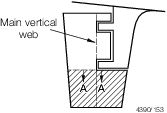
Figure 3.2.3 Semi-spade (mariner) type rudder
2.13.5 Connection
of rudder side plating to vertical and horizontal webs, where internal
access for welding is not practicable, is to be by means of slot welds
onto flat bars on the webs. The slots are to have a minimum length
of 75 mm and in general, a minimum width of twice the side plating
thickness. The ends of the slots are to be rounded. The space between
the slots is not to exceed 150 mm and welding is to be based on a
weld factor of 0,44.
2.13.7 Where
the fabricated mainpiece of a spade rudder is connected to the horizontal
coupling flange by welding, a full penetration weld is required.
2.14 Composite rudders
2.14.1 The requirements in this section are based on spade rudder constructions of composite
material with an aspect ratio not less than 3,0. Requirements for rudders with a
lesser aspect ratio will be specially considered. Requirements for rudders made from
a metal stock and composite blade will be specially considered. Requirements for
rudder arrangements with pintles will be specially considered.
2.14.2 The requirements in this section are based on construction using carbon/epoxy
composite but can be used for alternative constructions using other reinforcement
and matrix materials with due consideration for the properties of these
materials.
2.14.3 The requirements in this section are based on a structural arrangement with a single
stock of generally rectangular or trapezoid shape, extending from the upper bearing
through the lower bearing, down to not less than 0,75 times the height of the rudder
blade from the upper edge of the rudder blade. In this arrangement, the blade is
moulded around a core made of structural foam bonded to the fore and aft side of the
stock. The foam transfers the shear load to the stock. The bending in the horizontal
plane is taken by the skin of the blade.
2.14.4 The requirements are based on the stock being built from interleaved layers of
unidirectional fibres providing bending strength and biaxial fibres to provide
torsion and shear strength, wrapped around a foam core.
2.14.5 The limiting stress fraction, fσ, to be used in the
design is 0,25.
2.14.6 At and below the lower bearing, at any section along the length of the stock the
amount of biaxial material is to be sufficient to withstand the combined action of
shear load and torsion without exceeding the limiting stress fraction. The shear
load can be taken as:
|
Qbs |
= |
(fp/0.248)^3 *
(V+3)^2*Art*fR/10 kN |
Where
|
Art |
= |
area of rudder blade between the position of the section and the lower
end of the rudder, in m2 |
The torsion can be taken as:
V, fp, fR
see
Table 3.2.5 Position of centre of
pressure
2.14.7 At and below the lower bearing, at any section along the length of the stock the
amount of unidirectional material is to be sufficient to withstand the combined
action of bending moment, shear load and torsion without exceeding the limiting
stress fraction. The bending moment can be taken as:
where
|
ya |
= |
distance between the position of the section and the centroid of the
rudder area below the section, in metres. |
2.14.8 At and above the lower bearing, at any section along the length of the stock the
amount of biaxial material is to be sufficient to withstand the combined action of
shear load and torsion without exceeding the limiting stress fraction. The position
of the tiller is to be considered.
The shear load to be considered can be taken as the reaction force in the upper bearing.
|
Fub |
= |
Qbl *
(y1+(y3+hb)/2)/dyb
kN |
where
-
y3 is defined as in Figure 3.2.1 Rudder types
-
Fbl is Qbs taken at the lower bearing
position.
-
dyb is the vertical distance centre to centre between the
upper and lower bearing.
-
hb is height of lower bearing.
The torsion load can be taken as the torsion load in way of the lower bearing.
2.14.9 At and above the lower bearing, at any section along the length of the stock the
amount of unidirectional material is to be sufficient to withstand the combined
action of bending moment, shear load and torsion without exceeding the limiting
stress fraction. The bending moment can be taken as:
where
|
yu |
= |
distance between the position of the section and the centroid of the
upper bearing, in metres. |
2.14.10 The laminate in way of the mounting position of the tiller is to be suitably
protected and reinforced where necessary to take the loads from the tiller.
2.14.11 The shear strength of the foam and the bonding to the stock are to be not less than:
|
qbs |
= |
(fp/0.248)^3 *
(V+3)^2*fR/10 *
bb/bs N/mm2
|
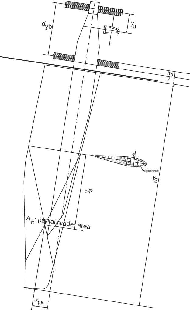
Figure 3.2.4 Composite rudder
dimensions
2.14.12 The laminate of the skin of the blade is determined by the envelope of the following
criteria:
- tensile stress due to load carried to stock
- compressive stress due to load carried from blade to stock
- wrinkling under this compressive stress
- minimal weight of reinforcement criterion as for shell laminate.
- below the lower end of the stock, strength required to support the part of the
blade below.
2.14.13 The lower end of the blade, extending below the stock, can be executed as a
sacrificial piece to save the stock in case of grounding.
2.15 Cast metal rudders
2.15.1 Where
rudders are cast, the mechanical and chemical properties of the metal
are to be submitted for approval. If the rudder stock is cast integral
with the rudder blade, abrupt changes of section and sharp corners
are to be avoided.
2.16 Lowest main bearing requirement
2.16.1 The design
of the lowest bearing is to comply with the requirements of Table 3.2.9 Lowest main bearing
requirements.
Table 3.2.9 Lowest main bearing
requirements
| Item
|
Requirement
|
| Lowest main
bearing
|
Depth Z
B, in mm
|
Minimum bearing
housing wall thickness, in mm
|
| 1,5d
s ≥ Z
B ≥ 1,0d
s
|
lesser of 0,2d
s or 100
|
| Bearing pressure (on the
projected area of the lowest main bearing), where the projected area is to
be taken as the length x diameter
|
Bearing
material
|
Maximum pressure, in
N/mm2
see Note 4
|
| Metal
|
7,0
|
| Synthetic
|
5.5
|
| Clearance in lowest main
bearing on the diameter (note should be taken of the manufacturer’s
recommended clearances, particularly where bush material requires
pre-soaking)
|
Bearing
material
|
Minimum
clearance, in mm
see Note 3
|
| Metal,
see Note 2
|
0,001d
s + 1,0
|
| Synthetic
|
0,002d
s + 1,0
but not less than 1,5
|
| Symbols
|
|
|
Note
1. Where web stiffening is fitted on the
bearing, a reduction in wall thickness will be considered.
Note
2. For bearings which are pressure
lubricated the clearance must be restricted to enable the pressure to
be maintained.
Note
3. Value of proposed minimum clearance is
to be indicated on plans submitted for approval.
Note
4. Proposals for higher pressures or
other materials will be specially considered on the basis of
satisfactory test results.
|
2.17 Bearings
2.17.1 Bearings are to be of approved materials and effectively secured to prevent
rotational and axial movement.
2.17.2 Where it is proposed to use stainless steel for liners or bearings for
rudder stocks and/or pintles, the chemical composition is to be submitted for approval.
Where the two surfaces are stainless steel materials, they should have suitable
resistance to galling. When stainless steel material is used, arrangements to ensure an
adequate supply of seawater to the bearing are to be provided to protect against
stagnant sea-water initiated corrosion.
2.17.3 Synthetic rudder bearing materials are to be of a type approved by LR.
2.17.4 When roller bearings are used on the rudder stock, the bearing must be of a size,
material and type suitable to sustain the loads from the rudder. Arrangement must be
made in the design to make them watertight.
2.18 Liners
2.18.1 Where
liners are fitted to rudder stocks or pintles, they are to be shrunk
on or otherwise efficiently secured.
2.18.3 When
stainless steel liners are used, arrangements to ensure an adequate
supply of sea-water to the liner are to be provided.
2.19 Pintles
2.19.2 Where
the lower pintle is housed above the rudder gudgeon see
Figure 3.2.5 Lower pintle housed above rudder gudgeon, and not below as shown
in Figure 3.2.6 Lower pintle housed below rudder gudgeon, C
PL is to be measured to the top of the gudgeon.
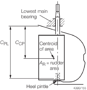
Figure 3.2.5 Lower pintle housed above rudder gudgeon
Table 3.2.10 Pintle requirements
| Item
|
Requirement
|
|
(1) Pintle diameter, see Note 2
|
|
| For
single pintle rudders and lower pintle of semi-spade rudders:
|
|
| but for
semi spade rudders need not be taken greater than A
R
|
| Upper
pintle on semi-spade rudders:
|
|
or 0,35A
R m2, whichever is the greater
|
| For
rudders with two or more pintles (except semi-spade rudders):
|
|
|
(2) Maximum pintle taper
|
Method of assembly
|
Taper (on diameter)
|
| Manual assembly, key fitted
|
1 in 6
|
| (pintle ≤ 200mm diameter)
|
| Manual assembly, key fitted
|
1 in 9
|
| (pintle ≤ 400mm diameter)
|
| For
keyed and other manually assembled pintles with diameters between 200mm and
400mm, the taper is to be obtained by interpolation.
|
| Hydraulic assembly, dry fit
|
1 in 12
|
| Hydraulic assembly, oil
injection
|
1 in 15
|
|
(3) Bearing length
|
Z
PB ≥ 1,2δPL mm
|
| May be
less for very large pintles if bearing pressure is not greater than that
given in (4), but Z
PB must not be less than 1,0δPL mm
|
|
(4) Bearing pressure (on projected area)
|
Bearing material
|
Pressure
|
| Metal
|
7,0
N/mm2
|
| Synthetic
|
5,5
N/mm2
|
| Using
force acting on bearing:
|
|
|
A
PL as for item (1)
|
|
(5) Gudgeon thickness in way of pintle (measured outside bush
if fitted)
|
but need not normally exceed 125mm
|
|
(6) Pintle clearance (note should be taken of the
manufacturer's recommended clearances particulary where bush material
requires pre-soaking). Value of proposed minimum clearance is to be
indicated on plans submitted for approval.
|
Bearing material
|
Minimum clearance, mm
|
| Metal
|
0,001δPL + 1,0
|
| Synthetic
|
0,002δPL + 1,0 but not
less than 1,5
|
| Symbols
|
|
δPL
|
= |
pintle diameter, in mm |
|
A
PL
|
= |
rudder area supported by the pintle, in m2
|
|
N
PL
|
= |
number of pintles on the rudder |
|
Z
PB
|
= |
pintle bearing length, in mm |
|
P
PL
|
= |
force acting on bearing, in kN |
|
b
G
|
= |
thickness of gudgeon material in way of pintle, in
mm |
|
Note
1. Proposals for higher pressures or
other materials will be specially considered on the basis of
satisfactory test results.
Note
2. The length of the pintle housing in
the gudgeon is not to be less than the maximum pintle diameter.
|
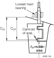
Figure 3.2.6 Lower pintle housed below rudder gudgeon
2.19.3 Special
attention is to be paid to the fit of the pintle taper into its socket.
To facilitate removal of the pintles, it is recommended that the taper
is to be not less than half the maximum value given in Table 3.2.10 Pintle requirements.
2.19.4 The distance
between the lowest rudder stock bearing and the upper pintle is to
be as short as possible.
2.19.5 Where
liners are fitted to pintles, they are to be shrunk on or otherwise
efficiently secured. If liners are to be shrunk on, the shrinkage
allowance is to be indicated on the plans. Where liners are formed
by stainless steel weld deposit, the pintles are to be of weldable
quality steel and details of the procedure are to be submitted.
2.19.6 The bottom
pintle on semi-spade (Mariner) type rudders are:
-
If inserted into
their sockets from below, to be keyed to the rudder or sternframe
as appropriate or to be hydraulically assembled, with the nut adequately
locked, or
-
If inserted into
their sockets from above, to be provided with an appropriate locking
device, the nut being adequately secured.
2.20 Bolted couplings
2.20.1 Rudder
coupling design is to be in accordance with Table 3.2.11 Rudder couplings to stock.
Table 3.2.11 Rudder couplings to stock
| Arrangement
|
Parameter
|
Requirement
|
| Horizontal
coupling
|
Vertical coupling
|
|
(1) Bolted couplings (see Notes)
|
n
|
≥
6
|
|
≥ 8
|
| δb
|
|
|
|
|
m
|
0,00071nd
Sδb
2
|
|
0,00043d
s
3
|
|
t
f
|
δb
see Note 1
|
|
δb
|
αmax
see Note 2
|
|
-
|
αas built
see Note 2
|
≤ αmax
|
-
|
|
w
f
|
0,67δb
|
|
0,67δb
|
|
(2) Conical couplings
|
θt
|
|
|
l
t
|
≥1,5d
s
|
|
|
|
|
w
|
|
|
P
u
|
Approximately equal to
|
|
P
o
|
Approximately equal to
|
|
σ
o
|
|
| Symbols
|
|
n
|
= |
number of bolts in coupling |
|
|
δb
|
= |
diameter of coupling bolts, in mm |
|
|
|
|
m
|
= |
first moment of area of bolts about centre of
coupling, in cm3
|
|
|
k
1
|
= |
the greater of k
s and k
f
|
|
|
|
|
|
|
|
|
R
|
= |
palm radius between rudder stock and connected flange,
not smaller than  , in mm , in mm |
|
|
t
f
|
= |
minimum thickness of coupling flange, in mm |
|
|
t
fa
|
= |
as built flange thickness, in mm |
|
|
αmax
|
= |
maximum allowable stress concentration factor |
|
|
αas built
|
= |
stress concentration factor for as built
scantlings |
| = |

|
|
|
w
f
|
= |
width of flange material outside the bolt holes, in
mm |
|
|
θ
t
|
= |
taper of conical coupling, on the diameter,
e.g.: |
| = |

|
|
 t
t
|
= |
length of taper, in mm |
|

|
= |
required mean grip stress, in N/mm2
|
|
|
w
|
= |
corresponding push-up of rudder stock, in mm |
|
|
P
u, P
o
|
= |
corresponding push-up, pull-off loads respectively,
in N |
|
|
σo
|
= |
minimum yield stress of stock and gudgeon material,
in N/mm2. σo is not to be taken greater than
70 per cent of the ultimate tensile strength |
|
 R
R
|
= |
effective weight of rudder, in N |
|

|
= |
mean diameter of coupling taper, in mm |
|

|
= |
diameter of coupling taper at any position, in
mm |
|

|
= |
mean external diameter of gudgeon housing, in mm |
|

|
= |
external diameter of gudgeon housing at any position,
in mm |
|

|
= |

|
|
|
f
|
= |

|
|
|
M
T
|
= |
maximum torque applied to stock, and is to be taken
as the greater of M
F, M
A or M
W. |
|
|
M
F
|
= |
P
L
X
PF x 106 Nmm in the ahead condition |
|
|
M
A
|
= |
P
L
X
PA x 106 Nmm in the astern condition |
|
|
M
W
|
= |
the torque generated by the steering gear at the
maximum working pressure supplied by the manufacturer, in Nmm.
M
W is not to exceed the greater of 3,0M
F or 3,0M
A
|
|
|
|
|
|
|
K
1, K
2, K
3
|
= |
constants depending on the type of assembly adopted as
follows: |
|
|
|
K
1
|
K
2
|
K
3
|
|
|
Oil injection
method
|
with
key
|
15
|
0,0064
|
0,025
|
|
|
Oil injection
method
|
without
key
|
15
|
0,0036
|
0,025
|
|
|
Dry fit method
|
with
key
|
12
|
0,0128
|
0,170
|
|
|
Dry fit method
|
without
key
|
12
|
0,0072
|
0,170
|
Note
1. For spade rudders with horizontal
coupling, t
f is not to be less than 0,25d
s.
Note
3. Where materials vary for individual
components, scantling calculations for such components are to be based
on d
s for the relevant material.
|
2.20.2 Where
coupling bolts are required they are to be fitted bolts. Suitable
arrangements are to be made to lock the nuts.
2.20.3 For rudders
with horizontal coupling arrangements, where the upper flange is welded
to the rudder stock, a full penetration weld is required and its integrity
is to be confirmed by non-destructive examination. Such rudder stocks
are to be subjected to a furnace post-weld heat treatment (PWHT) after
completion of all welding operations. For carbon or carbon manganese
steels, the PWHT temperature is not to be less than 600oC.
2.20.4 The connecting
bolts for coupling the rudder to the rudder stock are to be positioned
with sufficient clearance to allow the fitting and removal of the
bolts and nuts without contacting the palm radius, R, see
Figure 3.2.7 Rudder stock connection. The
surface forming the palm radius is to be free of hard and sharp corners
and is to be machined smooth to the Surveyor's satisfaction. The surface
in way of bolts and nuts is to be machined smooth to the Surveyor's
satisfaction.
2.20.5 For spade
rudders fitted with a fabricated rectangular mainpiece, the mainpiece
is to be designed with its forward and aft transverse sections at
equal distances forward and aft of the rudder stock transverse axis, see
Figure 3.2.7 Rudder stock connection.
2.21 Conical couplings
2.21.1 Where
a rudder stock is connected to a rudder by a keyless fitting, the
rudder is to be a good fit on the rudder stock cone. During the fit-up,
and before the push-up load is applied, an area of contact of at least
80 per cent of the theoretical area of contact is to be achieved,
and this is to be evenly distributed. The relationship of the rudder
to stock at which this occurs is to be marked, and the push-up then
measured from that point. The upper edge of the upper mainpiece bore
is to have a slight radius. After final fitting of the stock to the
rudder, positive means are to be used for locking the securing nut
to the stock.
2.21.2 Where
a keyed tapered fitting of a rudder stock to a rudder is proposed,
a securing nut of adequate proportions is to be provided. After the
final fitting of the stock to the rudder, positive means are to be
used for locking this nut.
2.22 Rudder carrier arrangements
2.22.1 The weight
of the rudder is to be supported at the heel pintle or by a carrier
attached to the rudder head. The hull structure supporting the carrier
bearing is to be adequately strengthened. The plating under all rudder-head
bearings or rudder carriers is to be increased in thickness.
2.23 Anti-jump collars
2.23.1 Suitable
arrangements are to be provided to prevent the rudder from lifting.
2.23.2 Jumping
collars are not to be welded to the rudder stock.
2.24 Drain plugs
2.24.1 Where
rudders are of plated construction, drain plugs are to be provided
to ensure that all compartments can be adequately drained. These plugs
are to be locked and details of their scantlings, arrangements and
position clearly indicated on the rudder plan.
2.25 Corrosion protection
2.25.1 All metalwork
is to be suitably protected against corrosion. This may be by coating
or, where applicable, by a system of cathodic protection, see
Ch 15 Corrosion Prevention of the Rules for Materials.
2.25.2 Metalwork
is to be suitably cleaned before the application of any coating. Where
appropriate, blast cleaning or other equally effective means are to
be employed for this purpose.
2.26 Dissimilar materials
2.26.1 Where
materials vary for individual components, they are to be compatible
to avoid galvanic corrosion. Scantling calculations for the components
are to be based on d
s for the relevant material, see
Table 3.2.6 Rudder stock diameter.
2.27 Internal coatings
2.27.1 Internal
surfaces of the rudder are to be efficiently coated or the rudder
is to be filled with foam plastics. Where it is intended to fill the
rudder with plastic foam, details of the foam are to be submitted.
2.28 Pressure testing
2.29 Tiller arms, quadrants
2.29.2 The steering
gear is to be mounted on a seat and adequately secured.
2.30 Connecting bars
2.31 Keys and keyways
2.31.1 Where
the tiller or quadrant is bolted, a key having an effective cross-sectional
area in shear of not less than 0,25d
SU
2 mm2 is to be fitted. The thickness of the key is to be not less
than d
SU/6 mm. Alternatively, the rudder stock
may be machined to a square section in lieu of fitting a key. d
SU is as defined in Table 3.2.6 Rudder stock diameter.
2.31.2 Keyways
are to extend over the full depth of the tiller boss.
2.31.3 Keyways
in the rudder stock are to have rounded ends and the corners at the
base of the keyway are to be radiused.
2.32 Stopping arrangements
2.32.1 Suitable
rudder stops are to be provided to limit the rudder angle to the desired
level port and starboard. These stops are to be of substantial construction
and efficiently connected to the supporting structure.
2.33 Novel designs
2.33.1 Where
rudders are of a novel design they may be specially considered on
the basis of the Rules. Alternatively the Builder's/designer's calculations
are to be submitted for consideration.
2.34 FRP double plated rudders
2.34.1 FRP double plated rudders are to have an internal structure of suitable strength and
material. Details of the rudder are to be submitted to LR for approval.
2.34.2 Where rudder blades are moulded in halves they are to be effectively joined together by
means of external overbonding of the joint or suitable mechanical fastening or
equivalent.
2.34.3 The internal structure of FRP double plated rudders may be a metallic framework. It is
to be made up of a mainpiece fitted with arms, within the blade, or an equivalent
arrangement. Both halves of the rudder blade moulding are to be effectively connected to
the metallic framework and mainpiece by either mechanical means or suitable bonded
connection.
2.34.4 When the internal structure of the FRP double plated rudder is metallic or of a
material that may detach from the blades at the point where the structure extends
outside the rudder blade, a suitable seal is to be provided to avoid ingress of
water.
2.34.5 Rudders
are to be filled with a suitable material upon completion of the join
up, details of the filler material are to be submitted.
2.34.6 The diameter
of the top of the rudder mainpiece must not be less than that of the
rudder stock. For spade rudders this diameter may be gradually reduced
for the lower third to not less than 75 per cent of the rudder stock
diameter.
2.34.7 The rudder
arms are to be efficiently attached to the mainpiece.
2.34.8 The laminate
weight of moulded fibre reinforced plastics double plate rudders is
to be determined by direct calculation, subject to a minimum laminate
thickness of 5 mm.
2.35 Rudder tube arrangements
2.35.1 The rudder
tube construction may be of aluminium alloy, steel, bronze or fibre
reinforced plastic.
2.35.2 The scantlings
of rudder tubes will be individually considered.
2.35.3 For steel
and aluminium hulls, the bottom shell in way of the rudder tubes is
to be additionally reinforced by means of an insert plate to increase
the bottom shell thickness by 50 per cent.
2.35.4 For F.R.P
hulls, the bottom shell laminate in way of the rudder tubes is to
be locally increased by 50 per cent. The increased thickness in way
of the rudder tube need not exceed the rule keel thickness requirement.
2.35.5 For F.R.P
sandwich hulls the shell in way of the rudder tube connection is to
be either:
-
Reduced from the
sandwich hull construction to single skin laminate for a distance
of a least three times the rudder tube diameter about the rudder stock
axis. The single skin region is to be additionally reinforced by a
minimum of 50 per cent of the sum of the inner and outer sandwich
laminate subject to this being at least equivalent to a 50 per cent
increase in thickness of the Rule minimum bottom shell laminate for
a single skin F.R.P. craft of the equivalent Rule length L
R. The reinforced laminate need not be greater than the Rule
keel laminate thickness.
-
Reduced from the
sandwich hull construction to a single skin laminate for a distance
of three times the rudder tube diameter about the rudder stock axis.
After bonding in the rudder tube to the single skin laminate the foam
core and inner skin are then reinstated.
-
Proposals to replace
the sandwich core with a core having higher core shear strength and
compressive strength than that of the adjacent structure prior to
bonding the tube to the inner and outer skins will be the subject
of special consideration.
2.35.6 The rudder
tube may be connected to the shell by bonding, bolting or welding
as applicable depending upon the construction material of the shell.
2.35.7 When
bonding in rudder tubes the bonding angle is to be not less than the
Rule minimum bottom shell weight. F.R.P. tubes are to be thoroughly
abraded and degreased prior to installation and laminating. Bonded
in metallic tubes are to be knurled in way of the bonding material
and thoroughly degreased prior to installation.
2.35.8 Where
rudder tubes are to be retained by bolting they are to be provided
with a substantial flange securely attached to the hull structure.
Where bolts are used, the nuts are to be suitably locked.
2.35.9 Where
rudder tubes are to be welded to hull insert plates full penetration
welding is required.
2.35.10 Rudder
tubes are to be supported by suitable brackets and deep floors to
avoid hard spots on the shell and to ensure continuity of the main
hull structure.
2.35.11 Rudder
bearings are to be secured against rotation within the rudder tubes
by suitable pinch bolting or keys. Details are to be submitted for
approval.
2.36 Watertight arrangement
2.36.1 In rudder trunks which are open to the sea, a seal is to be fitted above the
deepest load waterline, to prevent water from entering the steering gear compartment and
the lubricant from being washed away from the rudder carrier. If the top of the rudder
trunk is below the deepest waterline two separate seals are to be provided. Rudder trunk
boundaries, where exposed to the sea, are to have a corrosion protection coating applied
in accordance with the manufacturer's instructions.
2.36.2 Lip seals or 'O' rings may be used either in isolation or in combination
with one or other of the seal arrangements.
2.36.3 A watertight gland body may be used. It is then to be formed by the top of
the fabricated or cast rudder tube, the gland packing being retained against the top
bearing or a check in the wall of the rudder tube and is compressed by a gland packet
which may be of the flange type, screwed cap or other suitable arrangement.
2.37 In-water Survey requirements
2.37.1 Where
an *IWS (In-water Survey) notation is to be assigned, see
Pt 1, Ch 2, 3.8 Other hull notations, means
are to be provided for ascertaining the rudder pintle and bush clearances
and for verifying the security of the pintles in their sockets with
the craft afloat.
|