
Section
4 Structure design and construction requirements
4.1 Pod structure
4.1.1 Podded
unit struts and pod bodies may be of cast, forged or fabricated construction
or a combination of these construction methods.
4.1.2 Means
are to be provided to enable the propeller shaft, bearings and seal
arrangements to be examined in accordance with LR's requirements and
the manufacturer's recommendations.
4.1.3 When
high tensile steel fasteners are used as part of the structural arrangement
and there is a risk that these fasteners may come into contact with
sea-water, carbon-manganese and low alloy steels with a specified
tensile strength of greater than 950 N/mm2 are not to be
used due to the risk of hydrogen embrittlement.
4.1.4 For
steerable pod units, an integral slewing ring is to be arranged at
the upper extremity of the strut to provide support for the slewing
bearing.
4.1.5 The
strut is to have a smooth transition from the upper mounting to the
lower hydrodynamic sections.
4.1.6 For
fabricated structures, vertical and horizontal plate diaphragms are
to be arranged within the strut and, where necessary, secondary stiffening
members are to be arranged.
4.1.7 Pod
unit structure scantling requirements are shown in Table 4.4.1 Podded propulsion unit -
fabricated structure requirements. Where the scantling
requirements in Table 4.4.1 Podded propulsion unit -
fabricated structure requirements cannot
be satisfied, direct calculations carried out in accordance with Vol 2, Pt 4, Ch 4, 4.3 Direct calculations may be considered.
Table 4.4.1 Podded propulsion unit -
fabricated structure requirements
| Location
|
Requirement
|
Notes
|
| Strut external shell plating
|
Thickness, in mm, is to be not less
than:
t = 0,0063s
f (h
7
k)0,5
|
The minimum thickness of plating diaphragms and
primary webs within the strut is to be not less than the Rule requirement
for the strut external plating. For internal diaphragms, panel stiffening is
to be provided where the ratio of spacing to plate thickness
(s/t) exceeds 100. Where there are no secondary members,
s is to be replaced by S.
|
| Strut primary framing
|
The section modulus in cm3 is to be
not less than:
z = 7,75h
7
le
2
S
k
|
This does not apply to full breadth plate
diaphragms.
|
| Strut secondary stiffening
|
The section in cm3 is to be not less
than:
z = 0,0056h
7
le
2
s
k
|
This does not apply to full breadth plate
diaphragms.
|
| Cylindrical pod body external shell
plating
|
Thickness, in mm, is to be not less
than:
t = 3,0Rg (h
7
k)0,5
|
|
| Symbols
|
|
f
|
= |
panel aspect ratio correction factor = [1,1 –
s/(2500S)] |
|
h7
|
= |
(T + C
w + 0.014V
2) |
|
le
|
= |
effective span of the member under consideration, in
metres |
|
s
|
= |
the frame spacing of secondary members, in mm |
|
R
g
|
= |
mean radius of pod body tube, in metres |
|
S
|
= |
the spacing of primary members, in metres |
|
4.1.8 The
connection between the strut and the pod body should generally be
effected through large radiused fillets in cast pod units or curved
plates in fabricated pod units.
4.1.9 The
structural response under the most onerous combination of loads is
not to exceed the normal operational requirements of the propulsion
or steering system components.
4.1.10 For
cast pod structures, the elongation of the material on a gauge length
of 5.65  is to be not less than 12 per cent where S
o is the actual cross sectional area of the test piece. is to be not less than 12 per cent where S
o is the actual cross sectional area of the test piece.
4.1.11 In
castings, sudden changes of section or possible constriction to the
flow of metal during casting are to be avoided. All fillets are to
have adequate radii which should, in general, be not less than 75
mm.
4.2 Hull support structure
4.2.1 For
supporting the main slewing bearing outer faces, a system of primary
structural members is to be provided in order to transfer the maximum
design loads and moments from the podded propulsion unit into the
ship’s hull without undue deflection. Due account is also to
be taken of the loads induced by the maximum ship’s motions
in the vertical direction resulting from combined heave and pitch
motion of the ship. Account is also to be taken of any manoeuvring
conditions that are likely to give rise to high mean or vibratory
loadings induced by the podded propulsion unit. See
Vol 2, Pt 4, Ch 4, 2.2 Documentation required for design review 2.2.1.(d).
4.2.2 The
hull support structure in way of the slewing bearing should be sufficiently
stiff that the bearing manufacturer’s limits on seating flatness
are not exceeded due to hull flexure as a consequence of the loads
defined under Vol 2, Pt 4, Ch 4, 4.2 Hull support structure 4.2.1.
4.2.3 Generally,
the system of primary members is to comprise a pedestal girder directly
supporting the slewing ring and bearing. The pedestal girder is to
be integrated with the ship’s structure by means of radial girders
and transverses aligned at their outer ends with the ship’s
bottom girders and transverses, see
Figure 4.4.1 Hull support structure. Proposals to use alternative
arrangements that provide an equivalent degree of strength and rigidity
may be submitted for appraisal.
4.2.5 The
shell envelope plating and tank top plating in way of the aperture
for the podded drive (i.e. over the extent of the radial girders shown
in Figure 4.4.1 Hull support structure) is to be increased
by 50 per cent over the Rule minimum thickness to provide additional
local stiffness and robustness. However, the thickness of this plating
is not to be less than the actual fitted thickness of the surrounding
shell or tank top plating.
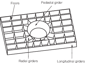
Figure 4.4.1 Hull support structure
4.2.6 The
scantlings of the primary support structure in way of the podded drive
are to be based upon the limiting design stress criteria specified
in Table 4.4.2 Direct calculation maximum
permissible stresses for steel fabricated structures, see
also
Vol 2, Pt 4, Ch 4, 4.3 Direct calculations 4.3.5. Primary
member scantlings are, however, not to be less than those required
by Vol 1, Pt 6, Ch 3, 7 Single bottom structures and Vol 1, Pt 6, Ch 3, 8 Double bottom structures.
Table 4.4.2 Direct calculation maximum
permissible stresses for steel fabricated structures
| Permissible stress values
|
| Location
|
Podded drive structure
|
Podded drive/hull
interface
|
| X-Y shear stress
|
0,26σo
|
0,35σo
|
| Direct stress due to bending
|
0,33σo
|
0,63σo
|
| Von Mises stress
|
0,40σo
|
0,75σo
|
| Localised Von Mises peak stresses
|
σo
|
σo
|
| Symbols
|
|
σo
|
= |
minimum yield strength of the material |
|
Note
1. The values stated above are intended
to give an indication of the levels of stress in the pod and ship
structure for the maximum loads which could be experienced during
normal service.
Note
2. If design is based on extreme or
statistically low probability loads, then proposals to use alternative
acceptance stress criteria may be considered.
|
4.2.7 The
pedestal girder is to have a thickness not less than the required
shell envelope minimum Rule thickness in way. Where abutting plates
are of dissimilar thickness, then the taper requirements of Vol 1, Pt 6, Ch 4 Hull Girder Strength are to be complied with.
4.2.8 In general,
full penetration welds are to be applied at the pedestal girder boundaries
and in way of the end connections between the radial girders and the
pedestal girder. Elsewhere, for primary members, double continuous
fillet welding is to be applied using a minimum weld factor of 0,34.
4.3 Direct calculations
4.3.1 Finite
element or other direct calculation techniques may be employed in
the verification of the structural design. The mesh density used is
to be sufficient accurately to demonstrate the response characteristics
of the structure and to provide adequate stress and deflection information.
A refined mesh density is to be applied to geometry transition areas
and those locations where high localised stress or stress gradients
are anticipated.
4.3.2 Model
boundary constraints are generally to be applied in way of the slewing
ring/ship attachment only.
4.3.3 The
loads applied to the mathematical model, see
Vol 2, Pt 4, Ch 4, 2.4 Global loads 2.4.1, are to include the self weight,
dynamic acceleration due to ship motion, hydrodynamic loads, hydrostatic
pressure, propeller forces and shaft bearing support forces. In situations
where a pod can operate in the flodded conditions or where flooding
of a pod adds significant mass to the pod, details are to be included.
4.3.6 For
cast structures, the localised von Mises stress should not exceed
0,6 times the nominal 0,2 per cent proof or yield stress of the material
for the most onerous design condition.
|