
Section
2 Hull girder strength
2.1 General
2.1.1 Longitudinal
strength calculations are to be submitted for all ships with a Rule
length, L
R, exceeding 50 m and are to cover
the range of operating conditions proposed in order to determine the
required hull girder strength. The still water, wave and dynamic bending
moments and shear forces are to be calculated in accordance with the
requirements of Vol 1, Pt 5, Ch 4 Global Design Loads
2.1.2 For
ships of ordinary hull form with a Rule length, L
R,
less than 50 m, the minimum hull girder strength requirements are
generally satisfied by scantlings obtained from local strength requirements.
However, longitudinal strength calculations may be required by LR,
dependent upon the form, constructional arrangement and proposed loading.
2.2 Bending strength
2.2.1 The
effective geometric properties of all critical transverse sections
along the length of the ship are to be calculated directly from the
dimensions of the section using only effective material elements which
contribute to the global longitudinal strength irrespective of the
grades of steel incorporated in the construction, see
Vol 1, Pt 6, Ch 4, 1.4 Calculation of hull section modulus
2.2.2 Where
higher tensile is fitted to satisfy global strength requirements,
the extent of higher tensile steel is to be as specified in Vol 1, Pt 6, Ch 2, 1.6 Higher tensile steel 1.6.3 Where a mix of steel
grades is used for plating and associated stiffeners, then the lower
of the steel grades is to be used for the derivation of the permissible
stresses, see 2.2.3.
2.2.3 The
longitudinal strength of the ship is to satisfy the following criteria
for the hogging and sagging conditions:
where
|
σp
|
= |
maximum
permissible hull vertical bending stress, in N/mm2
|
|
f
σhg
|
= |
limiting hull bending stress coefficient, derived as follows: |
| = |
(i) from 0,3L
R to 0,7L
R
f
σhg = 0,75
(ii)
for continuous longitudinal structural members aft of 0,3L
R and forward of 0,7L
R
f
σhg = 0,319 + 2,311 x/L
R –
2,974 (x/L
R)2
|
where
|
x |
= |
the distance,
in metres, from the F.P. for locations within the forward end of L
R and from the A.P. for locations within the aft end of L
R
|
|
f
σws
|
= |
1,2, limiting working stress coefficient |
| = |
NOTE, the σws criterion may be relaxed if it
can be demonstrated that either:
(i) a continuous fatigue
control monitoring system is to be adopted for the in-service life
of the ship
(ii) a fatigue design assessment procedure
is applied which demonstrates that a higher limiting working stress
coefficient, f
σws, may be applied
|
σ
o
(MS) = specified
yield stress, in N/mm2, for mild steel
σB, σD and σ
ws are
given in Table 4.2.1 Longitudinal component
stresses
f
hts and σ
o are defined
in Vol 1, Pt 6, Ch 4, 1.3 Symbols and definitions 1.3.1
Table 4.2.1 Longitudinal component
stresses
| Component stress type
|
Nominal stress
(N/mm2)
|
| Hull girder bending stress at strength deck, see Note 1
|

|
| Hull girder bending stress at keel, see Note 1
|

|
| Hull girder bending stress range, see Note 2
|

|
| Symbols
|
|
M
R = Rule bending moment, in kNm, given in Vol 1, Pt 5, Ch 4, 3.10 Hull girder design loads
|
|
M
WHog = hogging value of M
W, in kNm, given in Vol 1, Pt 5, Ch 4, 3.3 Vertical wave bending moments
|
|
M
WSag = sagging value of M
W, in kNm, given in Vol 1, Pt 5, Ch 4, 3.3 Vertical wave bending moments
|
|
Z
D = actual section modulus at deck, in m3
|
|
Z
B = actual section modulus at keel, in m3
|
Note
1. The hogging and sagging bending
moments are to be considered.
Note
2. The stress range at the keel or other
longitudinally effective material should be used if it is greater than
the stress range at the strength deck.
|
2.2.4 Special
consideration will be given to increasing the permissible stress outside
0,3L
R to 0,7L
R provided
that sufficient buckling checks are carried out.
2.2.5 The
requirements for ships of special or unusual design and for special
operations will be individually considered.
2.2.6 Where
different grades of steel are used then it should be ensured that
the design stress in each structural member is less than the permissible
hull vertical bending stress, i.e.
where
2.2.7 The
design stress due to hull girder bending, σhg, for
each structural member is given by
where
|
Z
i
|
= |
actual section modulus at structural element being considered,
in m3
|
M
R is given in Table 4.2.1 Longitudinal component
stresses.
2.3 Shear strength
2.3.1 The shear strength of all ships is to satisfy the requirements given in
this Section.
2.3.3 For ships with large openings in the side shell and/or a complex
arrangement of longitudinal bulkheads and decks is proposed, shear flow calculations or
direct calculation may be required.
2.3.4 Where shear flow calculation procedures other than those available within
ShipRight are employed, the requirements of Vol 1, Pt 6, Ch 3, 1.4 Equivalents are to be complied with.
2.3.5 The assessment of still water shear stresses is to take into consideration
the effectiveness of the following:
- continuous superstructures;
- the sizes and arrangements of window and door openings;
- access openings or cut-outs in side shell, longitudinal bulkheads,
etc.
2.3.6 The shear strength of the ship at any position along the length is to
satisfy the following criterion:
where
δο is to be taken as the minimum value of δi, and
|
τp
|
= |
maximum permissible shear stress, in N/mm2
|
| = |
f
τ
h
g
τ
ο
|
|
f
τ hg
|
= |
0,75f
hts, limiting hull shear stress coefficient |

|
= |
the inertia of the hull about the transverse neutral axis at the
section concerned, in m4
|
|
A
z
|
= |
the first moment of area of the longitudinal members about the
neutral axis, in m3
Only longitudinally effective members that lie between the
vertical level being considered and the vertical extremity are to be included |
|
δi
|
= |

|
|
t
i
|
= |
the plate thickness of the structural member at the vertical level
and section under consideration, in mm |
f
hts and τo are defined in Vol 1, Pt 6, Ch 4, 1.3 Symbols and definitions 1.3.1.
Table 4.2.2
k
i factors
| Hull
configuration
|
k
i factors
|
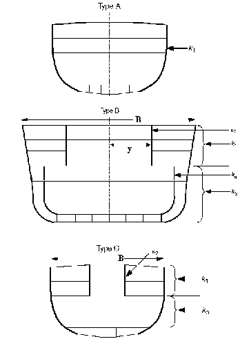
|
Member
1
k1 =
0,5
|
|
Member 1

Member 2

Member 3

Member 4

|
Member 1

Member 2

Member 3

|
| Symbols
|
Note i = structural index for different hull configurations
Note = 1 or 3, the side shell at the section under
consideration
Note = 2 or 4, the longitudinal bulkheads at the section of
consideration
Note
A
T = half the total effective shear area at the section
under consideration, in cm2, A
T= A
i
Note
A
i = the area of structural member i at the section under
consideration, in cm2
Note
y
is the distance of structural member 2 from the centreline
|
Note
1. For hull configurations not included
above, k
i factors are to be specially considered.
Note
2. Where it is necessary to increase the
thickness of the side shell or longitudinal bulkhead(s) to meet these
requirements, the original thicknesses are to be used in the
calculation of the cross-sectional areas A
i.
|
2.3.8 Where a plate is tapered, the permissible combined shear stress is not to
be exceeded at any point in way of the taper, see
Figure 4.2.1 Tapered plates
2.4 Torsional strength
2.4.1 Torsional
stresses are typically small for mono-hulls of ordinary form and can
generally be ignored.
2.4.2 The
calculation of torsional stresses and/or deflections may be required
when considering ships with large deck openings, unusual form or proportions,
or special operating modes which induce significant torsional stresses.
Calculations may in general be required to be carried out using direct
calculation procedures. Such calculations are to be submitted in accordance
with Vol 1, Pt 6, Ch 4, 1.5 General
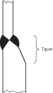
Figure 4.2.1 Tapered plates
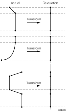
Figure 4.2.2 Calculation of A
i for non vertical
parts of structural members (referenced from Table 4.2.2)
2.5 Superstructures global strength
2.5.1 The
effectiveness of the superstructure in absorbing hull girder bending
loads is to be established where the first tier of the superstructure
extends within 0,4L
R amidships and where:
 1 > b
1 + 3h
1
1 > b
1 + 3h
1
where
 1
1
|
= |
length of
first tier, in metres |
|
b
1
|
= |
breadth of first tier, in metres |
|
h
1
|
= |
‘tween deck height of first tier, in metres |
2.5.2 For
superstructures with one or two tiers extending outboard to the ship’s
side shell, the effectiveness in absorbing hull girder bending loads
in the uppermost effective tier may be assessed by the following factor:
|
ηs
|
= |
7
((ε – 5) γ4 + 94 (5 – ε) γ3 + 2800 (ε – 5,8) γ2 + 27660 (9
– ε) γ) f(λ, N) x 10–7
|
-
where
f (1, N = 1) = 1
f (λ, N = 2) = 0,90λ3 – 2,17λ2 + 1,73λ + 0,50
and
|
N |
= |
1 if  2 < 0,7
 1
1
|
| = |
2 if  2 ≥ 0,7
 1
1
|
|
λ |
= |
 or 1, whichever is less or 1, whichever is less
|
|
ε |
= |
 or 5, whichever is less or 5, whichever is less
|
|
γ |
= |
 or 25, whichever is less or 25, whichever is less
|
 w
w
|
= |
 1 for N = 1
|
| = |
(2 1 +
1 +  2)/3 for N = 2
|
L
R is defined in Vol 1, Pt 6, Ch 4, 1.2 Hull girder strength notations 1.2.1, in metres
 1, b
1, h
1 are defined in Vol 1, Pt 6, Ch 4, 2.5 Superstructures global strength 2.5.1,
in metres.
1, b
1, h
1 are defined in Vol 1, Pt 6, Ch 4, 2.5 Superstructures global strength 2.5.1,
in metres.
 2
2
|
= |
length of
second tier, in metres. |
2.5.3 The
design stress due to hull girder bending, σhg, in the
uppermost effective tier at side may be derived according to the following
formula:
where
|
Zs
|
= |
section modulus at the structural element being considered,
in m3. The section modulus is to include the superstructure
tiers, assuming the tiers to be ηs effective.
|
2.5.5 The
uppermost effective tier may need to fulfil the requirements for strength
deck when the following applies:
where
ηs is defined in Vol 1, Pt 6, Ch 4, 2.5 Superstructures global strength 2.5.2
|
Z0
|
= |
section modulus of hull only at hull upper deck, in m3
|
 100
100
|
= |
moment of
inertia of hull and effective tiers, assuming tiers to be 100 per
cent effective, in m4
|
|
h
|
= |
height
from hull upper deck to uppermost effective tier, in metres. |
2.6 Buckling strength
2.6.1 The
buckling requirements in Vol 1, Pt 6, Ch 2, 3 Buckling are
to be applied to plate panels and longitudinals subject to hull girder
compression and shear stresses. The design stresses are to be based
on the design values of still water and wave bending moments and shear
forces and are given in Vol 1, Pt 6, Ch 4, 2.2 Bending strength 2.2.4 and Vol 1, Pt 6, Ch 4, 2.3 Shear strength 2.3.7 The design factors of safety
are given in Vol 1, Pt 6, Ch 5 Structural Design Factors
2.6.2 When
a Level 2 extreme strength assessment is applied, the Owner may specify
in the tailoring document that the buckling assessment of plate panels
subject to compressive stresses is not required. In this case the
buckling requirements of Vol 1, Pt 6, Ch 2, 3.3 Plate panel buckling requirements may
be relaxed. The requirements of Vol 1, Pt 6, Ch 2, 3.6 Shear buckling of stiffened panels for shear buckling and the remainder of Vol 1, Pt 6, Ch 2, 3 Buckling must always be complied with.
|