9.1.1 Loads
resulting from weapon launch may include recoil effects, blast and
missile efflux pressures, and in general will be impulsive. These
three types of load are estimated in different ways and will be covered
in turn.
9.1.2 Gun
and mortar recoil loads will generally be obtained from the manufacturer’s
documentation. If the natural frequency of the supporting structure
is more than four times the firing rate and at least 50 per cent higher
than the frequency derived from the time to maximum force, then a
dynamic load factor of 1,6 may be used for a first estimate. If the
gun is mounted immediately above an effective bulkhead then the structural
resonant frequencies will be much higher and a dynamic load factor
of 1,2 may be assumed. The stiffness of the supporting structure should
be adequate for the loads imposed and in accordance with the manufacturer’s
recommendations.
9.1.3 The
assessment of structure is to be made at the azimuth and elevation
of the gun that produces the maximum demands on each component of
the support structure. These will usually be ahead and abeam and at
0o and maximum elevation, although additional calculations
should be made at the 45o positions vertically and horizontally
against the resolved in-plane and normal elements of the load which
occur simultaneously.
9.1.4 The
load on the structure due to gun blast is in the form of a short-lived
transient over-pressure; values of this over-pressure should be available
in the manufacturer’s documentation for the weapon as curves
of pressure against distance from the gun muzzle. The pressure will
act only for a time of the order of 10ms so the structure, with a
much higher natural response period, is unable to react to the full
over-pressure and it is sufficient to design to an equivalent static
pressure using the dynamic load factors specified in Vol 1, Pt 6, Ch 2, 5 Dynamic loading. Guns with a high rate
of fire, typically greater than 30 rounds per minute, may induce a
forced vibration and will be specially considered.
9.1.5 Should
blast pressure curves not be available then a spherical approximation
to the equivalent static design pressure P
g can
be found from the following equation for φm values
in the range 80 mm to 120 mm
|
P
g
|
= |
2 (1+cos θ)2
 x 103 kN/m2 x 103 kN/m2
|
where
|
φm
|
= |
the
bore of the gun, in mm |

|
= |
the distance from the
muzzle of a point at which the pressure is required, in mm |
|
θ |
= |
the angle
to the centre-line of the barrel. |
As shown in Figure 2.9.1 Gun blast geometry
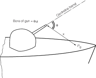
Figure 2.9.1 Gun blast geometry
9.1.6 Missile
efflux blast loading can be predicted by considering the rate of change
of momentum of the efflux where it strikes the structure under consideration.
However, when calculating the equivalent design load allowance must
also be made for the dynamic response of the structure. For practical
purposes therefore it is sufficient to design for the thrust averaged
over a cone of semi-angle b and the resultant equivalent
static pressure P
m may be found from
|
P
m
|
= |
f
DLF
 kN/m2 kN/m2
|
where
|
f
DLF
|
= |
a dynamic load factor relating to variations in the efflux pressure
and can be taken as 1,5 |
|
T
m
|
= |
thrust, in kN |
|
α |
= |
angle (25o < α < 90o) to the structure in degrees
|
|
A
|
= |
projected
area of cone in m2
|
|
β |
= |
the efflux
cone semi-angle in degrees and can be taken as 3o
|
As shown in Figure 2.9.2 Missile thrust geometry.
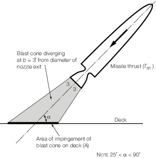
Figure 2.9.2 Missile thrust geometry
9.1.7 Missile
efflux will generally be at high temperature and may contain particulates.
Protection is to be provided for ship structure and equipment upon
which the efflux may impinge during launch.