
Section
5 Underwater explosion (shock)
5.1 General
5.1.1 There
are two principal loading mechanisms associated with the underwater
detonation of a conventional high explosive ordnance:
- shock wave loading;
- bubble flow loading.
5.1.2 The
energy released is in general, equally divided between shock wave
energy and the energy contained within the superheated high pressure
bubble of gaseous explosion products.
5.1.3 The
shock wave generated as the detonation wave passes into the water
is a highly non-linear pressure pulse which propagates at a speed
well in excess of the speed of sound in water (approximately 1500
m/s). However, within a few charge radii of the detonation point,
it can be mathematically defined as an acoustic pressure pulse travelling
at the speed of sound. Its amplitude falls off inversely with distance
and its profile can be characterised by a pulse which has an infinite
rise to a peak pressure followed by an exponential decay. The peak
value and decay rate at a given field point are given by the similitude
equations/coefficients for the explosive material.
5.1.4 In the
meantime, the gas bubble begins to expand against the ambient hydrostatic
pressure displacing water radially outward as incompressible flow.
As it expands, it loses pressure and temperature but the inertia of
the outwardly flowing water leads to an overshoot of the equilibrium
state so that at maximum bubble radius, the gas pressure is well below
the ambient. This initiates the collapse sequence, the gas bubble
is recompressed, slowly at first but then rapidly, to a minimum volume
by the hydrostatic forces. Because of the generation of a large pressure
in the bubble during this stage the bubble begins to expand again
and several other cycles may follow. The gas bubble and water interaction
can be thought of as a gas spring - mass system. It has a periodicity
associated with it but because of energy losses during the process,
the spring constant and mass changes over each cycle leading to a
change in the periodicity. At each minimum, that is, each recompression,
additional pressure pulses are emitted which become weaker with each
oscillation as shown in Figure 2.5.1 Shock wave bubble pulse.
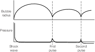
Figure 2.5.1 Shock wave bubble pulse
5.1.5 The
bubble is pulsating in a gravitational field and will have a tendency
to migrate to the water/air boundary (the free surface). However,
this bodily motion of the bubble centre may be influenced by the proximity
of other boundaries such as the seabed or a nearby ship structure.
The rate at which a bubble will migrate to the free surface is a function
of the buoyancy forces generated when it is at its maxima and of the
drag forces it experiences as it moves through the water. Because
these drag forces are small when the bubble is at its minima, it tends
to migrate vertically upwards more rapidly when at its smallest volume.
5.1.6 The
fluid flow generated by the bubble dynamics is an important loading
mechanism for a structure, within its sphere of influence. Normally
bubble loading can be ignored if the bubble never approaches within
a distance of around ten times the maximum bubble radius. The important
feature of the bubble loading is its low frequency which is ideally
suited to induce ship hull girder flexural motion. This flexural motion
is commonly referred to as hull girder whipping. This loading mechanism
is dealt with in Vol 1, Pt 4, Ch 2, 6 Whipping. If
the bubble is within one bubble radius of the ship structure, it is
likely to form a jet which will impact on the structure. This bubble
collapse mechanism will cause extensive local damage. It is generally
not possible to efficiently design against this loading event for
a NS2 or NS3 ship. For a NS1 ship
there may be sufficient residual strength to withstand such damage,
but the extent of the damage will need to be determined by a specialist
calculation and the capability of the hull using a residual strength
assessment, see
Vol 1, Pt 4, Ch 2, 7 Residual strength.
5.1.7 The
shock wave loading is greatest at a point on the structure nearest
to the detonation event and because of the fall-off with distance
and the narrowness of the pulse width, it can be thought of as a local
loading event. (In contrast, the bubble induced whipping of the hull
girder is considered a global loading event.) The remainder of this
section will focus on the shock loading event only.
5.1.8 There
are no simple analytical or numerical techniques for reliably determining
the shock resistance of a structure. A measure of the resistance to
shock loading can be achieved by good design of the details of the
structure to avoid stress concentrations which may lead to rupture.
It is also possible to ensure that the plating thickness is matched
to the assumed performance of the joints using a simple damage law.
The inertial loads on the ship's structure caused by the equipment
and its seatings can be determined by time domain analysis.
5.1.9 The
shock performance of a ship's hull structure can be assessed solely
by conducting shock tests (usually at scale). However, cost usually
precludes this approach and a better strategy is to combine tests
to determine failure criteria with numerical modelling using Finite
Element methods. This complementary experiment /numerical simulation
approach reduces the amount of testing required and also provides
a method for extrapolating to full scale from scaled experiments.
5.1.10 Generally,
for a normal ship structure, the explosion required to cause uncontrollable
flooding or total loss of propulsive power or loss of mission system
effectiveness (radars, electronics, etc.) is much less than that required
to cause failure of a hull designed for normal sea loads.
5.1.11 Due
to operational requirements, some vessel types, such as minesweepers,
will be required to resist repeated shock loading at a specified level
without degradation of the system or structural performance. Such
vessels will also be expected to survive a single attack at a considerably
higher shock loading level.
5.2 Threat level determination
5.2.1 The
actual threat level used in the calculation of performance and the
areas of the ship to be protected by this design method are to be
specified by the Owner and will remain confidential to LR.
5.2.2 Loading
levels may be specified with varying degrees of structural and system
degradation to define the shock performance of the vessel. An important
consideration is the balance that has to be achieved between system
functionality and structural performance.
5.2.3 Two
performance bounds can be considered for the shock response of structure:
- The first performance bound (lower bound) relates to the onset
of material yield (assuming that careful design has ensured that no
buckling will occur before this state is reached). This level is useful
to know as it may have consequences for system functionality. For
example, there may be problems associated with equipment mis-alignment
because of the permanent set of the supporting structure.
- The second performance bound (upper bound) relates to removal
or rupture of material; this being the loading level at which there
is no longer sufficient residual hull girder strength to resist normal
environmental loading. This is addressed in a separate assessment
which is defined by the residual strength notations RSA1, RSA2 or RSA3 in Vol 1, Pt 4, Ch 2, 7 Residual strength. In conventional naval ships, this upper bound will be significantly
higher; but there will be little, if any, system functionality.
5.3 Notation assessment methodology
5.3.1 The
shock performance required is to be specified by the Owner and is
to include requirements for:
- Local strength assessment;
- Detailed design;
- Seat design, shock mounts and system hangers;
- Hull valve design and integration;
- Global strength assessment;
- Shock qualification/testing of equipment;
- 1st of class shock trial.
It is recommended that seats, valves, piping and equipment are categorised
into:
- equipment required to be capable of operation after the specified shock
event;
- equipment that is required to be captive, with reduced or no operational
capability after the specified shock event;
- equipment which has no requirements after the specified shock event.
See also
Vol 2, Pt 1, Ch 1, 3.1 Categories 3.1.1.
5.3.2 Ships
that comply with the minimum or enhanced requirements of this Section
will be eligible for the shock notation SH.
5.3.4 For
the minimum shock capability, the design emphasis should focus on
maintaining a high level of system functionality and reducing the
risk of flooding.
5.3.5 For
the assignment of the SH notation, the minimum requirement
is for the structure to be designed to resist normal environmental
loads in accordance with the Rules. For NS1 ships, the
inherent ruggedness in the Rules is sufficient for the structure to
resist a low level threat. For NS2 and NS3 ships,
the integrity of the hull plate and stiffeners is to be verified,
using the simple formulae for pressure in Vol 1, Pt 4, Ch 2, 5.4 Local strength assessment 5.4.1, and comparing the response
to a specified standard. In addition, the hull valves below the waterline
are to comply with the requirements of Vol 1, Pt 4, Ch 2, 5.8 Design guidance for hull valves, piping and seals.
5.3.7 In addition
to the analysis, the SH notation can be enhanced by selecting
detail design requirements to reduce the risk of fracture initiation
and structural collapse, based on historical work on shock. Details
are provided in Vol 1, Pt 4, Ch 2, 5.5 Detail design guidance.
5.3.8 The SH notation may be further enhanced by undertaking shock trials
in accordance with established procedures, on the first ship in the
class. The magnitude of the test is normally less than the design
value for the hull and at a level that is appropriate for the equipment
and systems.
5.3.9 Global
assessment may be undertaken for the SH notation, using
the residual strength procedures outlined in Vol 1, Pt 4, Ch 2, 7 Residual strength with the extent of damage being defined from the
results of the local strength assessment rather than the damage radii.
For the RSA1 procedure, the damaged structure is to be
removed from the analysis. For the RSA2 or RSA3 procedure,
if the damage is limited, the geometry of the damaged structure can
be modelled and if the damage is severe, the structure is to be removed
from the analysis. The structure is considered acceptable when the
hull girder is able to withstand the design loads as specified in Vol 1, Pt 5 Environmental Loads.
5.4 Local strength assessment
5.4.1 For
the notation SH, a simple analysis can be performed which
allows the motion response at any point in the ship to be determined.
This can be derived from experimental results or the Taylor plate
equations given below. Once the motion response is known, the damage
potential can be determined by comparing the response to a specified
standard.
Maximum velocity
|
V
max
|
= |
 m/s m/s |
Time to maximum velocity
|
t
max
|
= |
 seconds seconds |
where
|
z
|
= |

|
|
u
|
= |

|
|
θ |
= |
decay constant
of explosive charge in seconds |
|
P
m
|
= |
peak pressure in N/mm2
|
|
ρ |
= |
density of
water in kg/m3
|
|
c |
= |
speed of sound
in water in m/s |
|
m
|
= |
structural
mass per unit area in kg/m3.
|
5.4.2 A more
complex assessment method can be used to enhance the SH notation.
Methods can be used which accurately model the physics of the shock
event. At the simplest level, a finite element model of the structure
coupled with a suitable boundary element from proprietary software
may be used.
5.4.3 For
complex ships such as multi-hull designs a boundary element approach
may not be suitable and a volume element approach should be used.
Also, if non-linear fluid behaviour is important (i.e. hull cavitation
or bulk cavitation), then a volume element approach should be used,
unless the finite element or boundary element code used has a suitable
cavitation model.
5.4.4 The
assessment method or analysis used should be validated against shock
trial results and the evidence made available. As an alternative to
analysis, full or large-scale shock trials of a section of the ship
can be used to validate the proposed design. For novel design arrangements
or ship types, a combination of trials and analysis may be necessary,
the requirements of which will depend on the threat level and type
of structure or ship design.
5.4.5 Any
finite element analysis performed for local strength assessment is
to be in accordance with the requirement of this Section for assignment
of the SH notation.
5.4.6 The
extent of the analysis model is to be from about 0,35L
R to 0,55L
R and encompass at least two
major compartments and three watertight bulkheads. It is to be sufficiently
large to avoid reflections within the structure from the boundaries,
for the threats considered. For the assessment of structural strength,
the structure need only be modelled to 1,0 m above the design water
line. If the model is to be used to determine equipment response,
all structure within that section should be modelled.
5.4.7 The
model, or versions of the model, should encompass representative integral
tank arrangements and hull penetrations, stabiliser inserts, hull
valves, the failure of which could lead to uncontrollable flooding.
Penetrations, the failure of which will not lead to significant flooding
or damage, need not be considered. The tanks and penetrations need
not actually be in the section under consideration but should be sufficiently
similar to represent structure outside the region modelled.
5.4.8 All
masses above 100 kg should be included in the model together with
an approximation of the mounting system if applicable.
5.4.9 The
model should include at least one major machinery item or raft.
5.4.10 The
response of hull panels depends upon a large number of variables which
are both design and attack geometry dependent. To simplify the task,
the following assumptions can be made:
- The charge detonates in the worst location, perpendicular to the
structure under consideration.
- All welding is continuous and there are no manufacturing or material
defects in the panels.
5.4.11 During
the analysis, appropriate elements are to be used to couple the fluid
medium and the structural model.
5.4.12 The
shock wave can be represented by an exponentially decaying, infinite
rise time pressure pulse which sweeps across the structure at the
speed of sound.
5.4.13 Non-linear
structural modelling can be used in finite element analyses. If used,
stiffeners should be modelled explicitly using shell elements of the
appropriate thickness. Stiffener flanges should be modelled with at
least two elements per half width or flange. Initial imperfections
in the hull plating are to be taken into account prior to the dynamic
loading analysis.
5.4.14 The
structure is considered acceptable when:
- Elastic deflections are less than the temporary limits of machinery
and systems.
- Permanent deflections are less than the limits of machinery and
systems.
- Deflections and strain are less than the limits of the structure
or applicability of the analysis method.
5.5 Detail design guidance
5.5.1 For
enhanced shock performance, any of the following design details can
be included in the design, which is based on historical shock testing
and experience.
5.5.2 Tank
boundaries are to be of equivalent scantlings to the hull boundaries.
5.5.3 Intermittent
welding is not to be used on hull girder structure or tank boundaries
below the water line or for 1 metre in way of the deck and shell connections.
5.5.4 Structural
discontinuities are to be avoided and in general a minimum taper of
1:4 is to be applied to changes of structural section.
5.5.5 Bar
keels are not to be fitted.
5.5.6 Tanks are to be integral with the ship's structure. For free standing tanks
greater than 100 litres, calculations demonstrating the capability of the tank and
supporting structure are to be submitted.
5.5.8 The
size of longitudinal members passing through, or ending on, bulkheads
are to be as small as possible, though still complying with the appropriate
scantling requirements of Vol 1, Pt 6, Ch 3 Scantling Determination. Bulkhead stiffeners are to be fitted perpendicular to
the shell plating.
5.5.9 Where
deep longitudinal members are unavoidable, their connection to the
bulkhead will be specially considered.
5.5.10 Bottom
longitudinals are to be of a uniform size. Alternate large and small
longitudinals are to be avoided as they may lead to high shear forces
in the bulkhead.
5.5.11 Access
holes in all primary framing members are to be avoided in areas of
high shear stress. Where they are essential to the operation of the
ship they are to be circular and fitted with appropriate stiffening
or compensation.
5.5.12 Frames
on the bilge are to be provided with adequate lateral support, consideration
should be given to the fitting of a shock stringer.
5.5.13 Lapped
connections are not to be used to connect frames to floors.
5.5.15 In
transversely framed ships, bulkhead stiffeners are to be terminated
on a shock stiffener welded to the bulkhead, parallel to, and spaced
500 mm from the shell. The bulkhead plating thickness is to be suitably
increased in way. The shock stringer and bulkhead plate may be replaced
by a web frame of suitable scantlings.
5.5.16 Bulkhead
penetrations are to be grouped, away from the side shell and kept
above the water line as far as is practicable.
5.5.17 Shell
frames and deck beams are to be fitted in such a way as to minimise
misalignment. Brackets where fitted are to be radiused and fitted
with soft toes.
5.5.18 Where
the vessel is to be subjected to very high levels of shock, the following
details can be included in the design.
5.5.19 Pillar
bulkheads are to be used below the waterline in place of pillars.
5.5.20 It
is recommended that symmetric stiffeners should be fitted to the to
the underwater portion of the shell envelope.
5.5.21 Where
a transverse framing system is used, the shock capability of the structure
will be specially considered. Calculations supporting the use of particular
design details are to be submitted.
5.5.22 All
bulkhead stiffeners are to end on longitudinals, see
Figure 2.5.2 Bulkhead stiffening. An increased thickness
margin strake on bulkheads of thickness not less than 80 per cent
of the adjacent shell plate thickness, the thickness of the adjacent
shell stiffener or 6,5 mm. The margin plate is to have a width not
less than 1,5 times the adjacent stiffener spacing or four times the
depth of adjacent shell stiffeners.
5.5.24 Where
brackets are fitted, similar tolerances to Vol 1, Pt 4, Ch 2, 5.6 Seat design 5.6.5 are to be applied subject
to a suitable area being provided for weld fillet, see
Figure 2.5.3 Bracket connections. Tripping brackets or
intercostal stiffeners should be used to stabilise the frame at the
bracket toes. Brackets are to be radiused and fitted with soft toes.
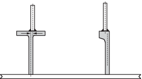
Figure 2.5.3 Bracket connections
5.5.25 The
cross-sectional area of the bulkhead stiffeners at their outer ends
in way of the margin plate should not be less than 60 per cent of
the area of the web of the hull longitudinals to which they are attached.
To achieve this requirement, the bulkhead stiffeners may be tapered
between the outer end and the point at which the size is the minimum
required to withstand lateral pressure. The slope of the taper is
to be such that:
Ax > 0,6AL- 2tx/3
where
|
A
x
|
= |
cross-sectional area of the bulkhead stiffener at a distance
x from its outer end |
|
A
L
|
= |
web area of the longitudinal, and t is the bulkhead plating
thickness at x. |
5.5.26 The
short stiffeners above the turn of bilge should be on the same side
of the bulkhead as the main bulkhead stiffeners and should end on
such a stiffener, see
Figure 2.5.2 Bulkhead stiffening. Where necessary, an additional diagonal stiffener may
be worked to facilitate the arrangement.
5.6 Seat design
5.6.1 The
shock notation may be enhanced by specifying that some or all of the
equipment seating is to be designed to resist shock loading. Seat
design should take account of the acceleration and deceleration from
the shock wave; the magnitude of the shock acceleration will depend
on the equipment mass, position in the ship and mounting arrangements.
The seat design methodology is to be in accordance with a specified
standard. The selection of seats to be assessed will depend on the
equipment supported and the compartment in which it is situated.
5.6.2 Minor
seats should be assessed to ensure that equipment remains captive.
Detail design requirements such as minimum thickness, alignment, and
free edge support can be specified to improve shock performance. In
the absence of information, minor seats can be considered as those
with equipment mass below 100 kg.
5.6.3 Seats
which are not classed as minor are to be assessed for shock loads
using acceleration values appropriate to the region of the ship in
which the equipment is installed. Large items of equipment where the
seat is integrated into the ship’s structure will normally require
a finite element analysis to assess the strength of the seat. Where
these seats are adjacent to the hull or an integrated tank, the fluid
structure interaction may need to be modelled. See
Vol 1, Pt 4, Ch 2, 5.4 Local strength assessment.
5.6.4 The
shock accelerations are to be specified by the Owner. In general,
accelerations will be specified for the following regions of the ship:
-
within 2,0 m of
the wetted hull;
-
main transverse
bulkheads and decks below the strength deck;
-
above strength
deck and superstructures.
Shock accelerations can be scaled using a factor for different
equipment based on its category of use.
5.6.5 For
each equipment seat to be assessed, a report is to be provided containing
the following information:
-
equipment mass
and centre of gravity;
-
location in vessel;
-
mounting system;
-
spatial clearances
around the mounted equipment;
-
captivity requirements;
-
relevant excitation
frequencies from mounted equipment in the case of reciprocating or
rotational machinery;
-
calculations demonstrating
maximum stress and displacement, under vertical acceleration, vertical
deceleration and athwartships accelerations. For non-linear analyses,
strain rates are to be provided;
-
equipment alignment
requirements, as appropriate.
5.6.6 As a
minimum, the following seat load cases are to be assessed:
-
bolts; pull through,
tensile, shear and bearing strength;
-
seat flange; flange
bending and top plate weld area;
-
seat web; buckling
and overturning;
-
deck; seat weld
area if less than flange.
5.6.7 Stress and strain are to be assessed against criteria appropriate for the
seat material and loading rate. The first fundamental mode of vibration of the seat
including equipment is to be greater than 10 times the shock mount rated natural
frequency to provide a sufficiently rigid base for the shock mount. In the absence of
specific information, for steel, the data in Table 2.5.1 Allowable stresses for seat
design may
be used:
Table 2.5.1 Allowable stresses for seat
design
|
|
Tension
|
Bending
|
Shear
|
| Plastic deformation of seats
|
1,3 σps
|
1,3 σps
|
1,0 σps
|
| Long loading times ≥5 ms (elastic deformation
only)
|
1,0 σps
|
1,0 σps
|
0,8 σps
|
| Short loading times <5 ms
(elastic deformation only)
|
1,2 σps
|
1,5 σps
|
0,9 σps
|
where
|
σps
|
= |
static 0,1% proof stress |
The values in this Table are applicable to mild and high tensile steel
grades up to a yield strength of 400MPa.
|
5.7 Shock mounts
5.7.1 All
shock mounts are to be of an approved type. Approval is to be undertaken
by organisations approved by the Naval Administration. Approval documentation
should contain the following information in accordance with NATO document
ANEP63:
-
nature and application
of the mount, including generic type, application, load range, shock
displacement, environmental constraints and frequency range;
-
description of
the mount assembly, including the complete assembly, the mount and
the associated components;
-
details of the
mount standard assembly and installation;
-
physical size,
mass and dimensions;
-
performance data
as listed in Table 2.5.2 Shock mount
characterisation;
-
details of the
mount testing process, including method of force generation, number
of mounts used/shots used, mount supplier, validation, mount permanent
deflection, details of test facility and date of testing;
-
mount specific
protection, installation, inspection and maintenance requirements;
-
any applicable
historic data, i.e. changes to the mount details over time. For example,
changes of material, etc.
Table 2.5.2 Shock mount
characterisation
| Mount
size number
|
|
1
|
| Nominal
load
|
kg
|
|
| Static stiffness
|
- Vertical V
- Horizontal H
A
- Horizontal H
R
|
|
|
| Dynamic stiffness
|
- Vertical V
- Horizontal H
A
- Horizontal H
R
|
|
|
| % of
critical damping
|
| Vertical
static displacement at nominal load
|
mm
|
|
| Natural frequencies
|
- Vertical V
Horizontal H
A
Horizontal H
R
|
|
|
| Dynamic
magnification at resonance
|
–
|
|
| Shock displacement capacity
|
- Vertical V
- Horizontal H
A
- Horizontal H
R
|
|
|
| Maximum transmitted acceleration at
nominal load
|
- Vertical V
- Horizontal H
A
- Horizontal H
R
|
|
|
| Range of
validity of mount surface/best fit governing equation (where applicable)
relative to unloaded condition
|
±mm
|
|
| Required
support stiffness
|
N/m
|
|
| Required
support strength
|
N
|
|
5.8 Design guidance for hull valves, piping and seals
5.8.1 Hull
valves below the waterline are to be of an approved type. Approval
is to be undertaken by organisations approved by the Naval Administration.
Approval documentation should contain the following:
-
details of the
valve body, main components and securing arrangement to the hull,
including bolt material grade and tightening torque;
-
details of the
valve testing process, including method of force generation, number
of tests, validation, details of test facility and date of testing.
5.8.2 Only
materials with sufficient ductility to avoid fracture under shock
conditions are to be used. Materials should be able to withstand high
stresses for very short periods without exhibiting brittleness. Valve
bodies are not to be made from materials with an elongation of less
than 10 per cent. There should be adequate material in way of the
valve seat to prevent distortion.
5.8.3 In general,
the valve body should be as symmetrical as possible with no rapid
changes in section; web stiffeners should not be incorporated. Spindles
should be as short as possible. Square threads or sharp thread run-outs
are to be avoided. Handwheels should be as light and small as possible.
5.8.4 The
weight of the actuator is to be considered in the design of the valve
and its connection to the hull. The actuator can form a considerable
proportion of the overall weight of the valve.
5.8.5 Consideration
should be given to the attached piping and its capacity to withstand
shock:
-
Detachable pipe
connections should be kept to the minimum necessary for installation
and maintenance requirements;
-
Flanged and welded
connections are to be used adjacent to the hull valve. Adjacent piping
is to be designed to allow the valve and hull to flex under shock
with limited restraint;
-
Where necessary,
piping shall be supported with shock resistant mounts at a sufficient
number of locations commensurate with the design shock level. The
selection of shock mounts should consider displacement capability, see
Vol 1, Pt 4, Ch 2, 5.7 Shock mounts. The response
of the piping relative to equipment should be considered. Sufficient
space between equipment and piping should be provided to ensure they
do not contact each other in a shock scenario;
-
The routing of
piping should be developed to minimise the number and size of penetrations
through bulkheads, see
Vol 1, Pt 4, Ch 2, 5.8 Design guidance for hull valves, piping and seals 5.8.11;
-
The consequences
of leakage from piping and fittings should be investigated;
-
Brackets should
not be welded direct to steel piping;
-
Adequate division
of vital piping systems to isolate damage should be considered;
-
The shock resistance
of flanged connections should consider bolt preload, anti-rotational
locking devices where appropriate and performance of gaskets.
5.8.6 The
sealing arrangement between the valve and the hull insert is to be
suitable for shock loading and able to accommodate elongation of the
securing studs.
5.8.7 Hull
valve designs can be approved by the following methods:
-
physical testing;
-
semi-empirical
methods;
-
direct calculation.
5.8.8 Physical
shock testing may be used to assess the valve. Physical testing is
to take account of the attachment to the hull and possible combinations
of hull scantlings, stiffener spacing, materials, etc.
5.8.9 Recognised
semi-empirical methods may be used to assess the valve.
5.8.10 Validated
numerical methods may be used to assess the valve. Where used, they
are to take account of the following criteria:
-
asymmetry in
the valve and piping assembly;
-
dimensions of
the hull insert/pad;
-
use of sea tube
between the valve and hull insert;
-
hull scantlings
and stiffener/frame spacing;
-
plasticity in
the hull and valve assembly;
-
the effective
mass of the valve, actuator and piping;
-
the valve to
hull securing arrangement, taking into account fit and pre-stress
effects;
-
dynamic properties
of materials;
-
the effect of
any surrounding equipment or masses.
Sea tubes of unusual material, GRE for example, or unusual configuration
are to be assessed by physical shock testing and not assessed by numerical
simulation.
5.8.11 The
potential for leakage from seals/glands under shock loading, and the
consequences of leakage, are to be considered. The shock resistance
of vital seals/glands, including stern-tube seals, is to be validated
by shock qualification testing. The sealing efficiency of stern-tube
seals should not be compromised by the anticipated axial, radial and
angular shaft movements commensurate with the design shock level.
|