
Section
4 Construction Monitoring
4.1 Construction Monitoring notation – CM
4.1.1 The
Construction Monitoring (CM) notation may be assigned
if extended controls on structural alignment, fit-up and workmanship
standards are applied to critical areas, as identified during the
design of the ship. Construction Monitoring is applied primarily to
verify the quality of workmanship required to improve the fatigue
resistance of critical details, though other construction quality
requirements can be specified in the CM plan.
4.1.2 The
fatigue life of structural details can be adversely affected by a
variety of factors, including workmanship defects. Criteria for workmanship
defects can be considered in the CM plan. The most common factors
that impact on fatigue are:
-
Misalignment of
structural members; i.e. poor fit-up;
-
Welding defects;
-
Materials defects;
-
Stress concentrations
resulting from incorrect geometry of structure, inadequate plate edge
finish or generally poor manufacturing;
-
Erroneous cut-outs
due to inappropriate routing of systems;
-
Discontinuity
of structural members.
4.2 Identification of critical areas
4.2.1 A critical
area is generally a structurally significant item or structural joint
that has been subjected to an enhanced calculation or assessment.
As a consequence, the performance of the item or joint will be influenced
by the workmanship and fit-up in the building yard. In some areas,
where there are high cyclic stresses, an enhanced workmanship and
alignment standard is required in order to achieve the specified design
hull fatigue life.
4.2.3 Critical
areas may also be identified by LR from one of the following optional
assessments. In general, these will be associated with reinforcement
and alignment of specific critical joints; they will not be associated
with general deformation criteria:
-
Extreme Strength
Assessment (ESA), specified in Vol 1, Pt 6, Ch 4, 3 Extreme Strength Assessment, ESA;
-
Residual Strength
Assessment (RSA), specified in Vol 1, Pt 6, Ch 4, 4 Residual Strength Assessment, RSA;
-
Whipping Assessment
(WH), specified in Vol 1, Pt 4, Ch 2, 6 Whipping.
4.2.4 In addition,
critical areas may be identified by the designer, Naval Administration
or Owner from one of the following:
-
Known areas of
high stress identified by structural engineers;
-
Areas that have
experienced failure on similar ships in service;
-
Structures with
specific alignment requirements; e.g. masts, shaft brackets.
4.2.5 The
critical areas, locations and assessment criteria are to be detailed
in the Construction Monitoring plan. The plan should also contain
templates to be used to record specific alignment requirements. The
CM plan may be supported by a high-stress key plan identifying critical
regions on the ship.
4.2.6 Development
of the CM plan is the responsibility of the designer; LR will identify
the critical locations to be subjected to monitoring, following appraisal
of the assessments identified in Vol 1, Pt 3, Ch 6, 4.2 Identification of critical areas 4.2.2 and Vol 1, Pt 3, Ch 6, 4.2 Identification of critical areas 4.2.3 above. In general, areas with
stress ranges greater than σws, see
Vol 1, Pt 6, Ch 4, 2.2 Bending strength 2.2.3, and areas where
general or detailed fatigue analysis has been undertaken will be listed
in the appraisal documentation. LR may develop the CM plan on behalf
of the designer, if so requested.
4.2.7 It is
recommended that the areas for Construction Monitoring be identified
and the criteria developed in a workshop with the Owner, Naval Administration,
Builder and LR.
4.3 Construction monitoring criteria
4.3.2
Normal
alignment is assigned to structure which requires an enhanced
level of survey above the normal survey requirement but does not require
enhanced levels of alignment above the agreed production standard,
such as the Naval Survey Guidance for Steel Ships:
-
Structure will
be inspected by the Builder, before welding, for compliance with the
general shipbuilding tolerances laid down in the agreed production
standard.
-
A representative
sample of alignment measurements will be undertaken by LR during the
survey to confirm compliance with the agreed production standard.
-
Where there are
non-compliances, the relevant shipyard department will be requested
by LR to undertake full measurements and to produce a report for review
by LR which details the non-compliances.
4.3.3
Enhanced
alignment is assigned where critical areas have enhanced alignment
requirements to maintain structural performance:
-
The relevant shipyard
department will be required to provide a report, based on templates
in the CM plan, detailing the achieved alignment at each location.
-
LR will review
the alignment report and request check measurements as necessary to
confirm the results.
-
The maximum allowable
misalignment between the interconnection of structural members is
to be 15 per cent of the thinner of the members being connected. This
alignment criterion is to be applied where longitudinally effective
structure is butted; e.g. plating at ring butts, longitudinal butts, see
Figure 6.4.1 Alignment criterion.
-
For all cruciform
joints, the maximum allowable misalignment between the interconnection
of structural members is to be 20 per cent of the thinner of the members
being connected. This alignment criterion is to be applied where there
is alignment through a thickness; e.g. intercostal longitudinal bulkheads
through a transverse bulkhead, bilge keel plate alignment with internal
structure through shell plating, see
Figure 6.4.2 Cruciform joints.
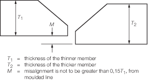
Figure 6.4.1 Alignment criterion
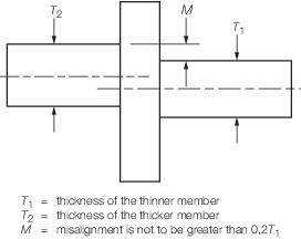
Figure 6.4.2 Cruciform joints
4.3.4
Specific
alignment is assigned where there are specific alignment criteria
identified by the designer which need to be verified by LR:
-
the relevant shipyard
department will be required to provide a report detailing the achieved
alignment at each location;
-
LR will review
the alignment report and request check measurements as necessary to
confirm the results;
-
the alignment
criteria and templates, where appropriate, are to be defined by the
designer for each critical area defined.
4.3.5
Close-up
inspection is assigned to structure which has no specific alignment
requirement but requires an increased level of inspection; for example,
to verify correct plate thickness or maximum permitted plate deformation.
Close-up inspection may be required to verify a particular or unusual
structural feature:
-
Structure will
be subject to an enhanced close-up visual inspection by LR Surveyor(s).
-
Dry surveys should
identify where units or compartments contain construction monitoring
points. These are to be identified by the Builder as a specific witness
point.
4.3.6 Non-destructive
examination, in addition to the general levels of NDE required in Vol 1, Pt 6, Ch 6 Material and Welding Requirements, may be specified by the designer
for critical areas, which LR will verify:
-
The relevant shipyard
department will be required to undertake the additional NDE required
at each location and record the results.
-
LR will review
and audit the NDE measurements as necessary to confirm the results.
4.4 Construction Monitoring survey
4.4.1 Construction
Monitoring is a process for monitoring workmanship standards and alignment
in critical areas. It is the Builder’s responsibility to carry
out the necessary checks and document the results for relevant critical
locations, irrespective of the Surveyor(s) attendance at hold points.
Shipyard personnel are responsible for the inspection and recording
of all CM requirements, in accordance with the approved CM plan.
4.4.2 LR will
provide third party inspection to confirm that the critical areas
to be covered by CM conform to the required/agreed standards based
on check inspections and audit activities. Where LR undertakes a CM
inspection to verify the implementation of the CM plan, it will cover:
-
weld specification
in terms of type, size and finish/treatment, including:
-
fit-up and alignment
before commencement of welding;
-
alignment
after application of first root run;
-
back gouging;
-
final welding
and alignment;
-
stress relief
grinding of weld profile (where required for enhanced fatigue performance);
-
the continuity
of structural members, where required;
-
plate edge radius
and roughness;
-
joints for radius
and tapering;
-
openings and penetrations
for radius corners.
4.4.3 LR will
review all of the specific CM records, as defined in Vol 1, Pt 3, Ch 6, 4.3 Construction monitoring criteria, and in a few cases request that
measurements be presented. It is not intended that the attending Surveyor(s)
witness each stage of the fabrication process for every critical area,
except during the early stages of construction whilst the process
is being established.
4.4.4 CM activities
will generally be undertaken in conjunction with routine dry surveys
required for all construction units. A few specific CM items require
measurement by the shipyard; these are described as Enhanced or Specific
Alignment.
4.4.5 Non-compliances
will not be permitted in the critical areas identified within the
CM plan. Where defects are identified within defined critical sections,
LR is to agree the remedial action to be taken with the Shipbuilder
before rectification is commenced.
4.4.6 On satisfactory
completion of all surveys and measurements, LR Surveyor(s) will recommend
the assignment of the CM notation.
|