
Section
7 Towing arrangements
7.1 Definition
7.1.1 Towing
can be defined as either receiving motive assistance from, or rendering
it to, another vessel.
7.2 Application
7.2.1 The
towing arrangements specified in this section are applicable to NS1,
NS2 and NS3 category ships carrying the corresponding optional towing
arrangement notation.
7.2.2 The
strength of strong points, fittings and machinery are to be proof
tested unless type approved.
7.2.3 In general,
ships complying with the requirements of this section will be eligible
to be classed with the notation TA1,
TA2 or TA3.
7.2.7 These
three levels of towing arrangements in 7.2.4 to 7.2.6 recognise towing
a ship of similar displacement at 6 knots in defined environmental
conditions (see
Table 5.7.3 Environmental conditions) and are appropriate for the weather conditions found
in the equivalent service areas, i.e. TA1 corresponds
to the weather conditions found with service area notation SA1.
7.2.10 Towing
operations are to be in accordance with the towing, mooring and arrangements
plan or equivalent information which is required to be placed on board. See
Vol 1, Pt 3, Ch 5, 7.4 Information required.
Table 5.7.1 Equipment - Minimum length and
breaking strength of towlines
| Equipment number
|
Equipment Letter
|
Towline
|
| Exceeding
|
Not Exceeding
|
Minimum length, in
metres
|
Minimum breaking
strength, in kN
|
| 50
|
70
|
A
|
180
|
98
|
| 70
|
90
|
B
|
180
|
98
|
| 90
|
110
|
C
|
180
|
98
|
| 110
|
130
|
D
|
180
|
98
|
| 130
|
150
|
E
|
180
|
98
|
| 150
|
175
|
F
|
180
|
98
|
| 175
|
205
|
G
|
180
|
112
|
| 205
|
240
|
H
|
180
|
129
|
| 240
|
280
|
I
|
180
|
150
|
| 280
|
320
|
J
|
180
|
174
|
| 320
|
360
|
K
|
180
|
207
|
| 360
|
400
|
L
|
180
|
224
|
| 400
|
450
|
M
|
180
|
250
|
| 450
|
500
|
N
|
180
|
277
|
| 500
|
550
|
O
|
190
|
306
|
| 550
|
600
|
P
|
190
|
338
|
| 600
|
660
|
Q
|
190
|
370
|
| 660
|
720
|
R
|
190
|
406
|
| 720
|
780
|
S
|
190
|
441
|
| 780
|
840
|
T
|
190
|
479
|
| 840
|
910
|
U
|
190
|
518
|
| 910
|
980
|
V
|
190
|
559
|
| 980
|
1060
|
W
|
200
|
603
|
| 1060
|
1140
|
X
|
200
|
647
|
| 1140
|
1220
|
Y
|
200
|
691
|
| 1220
|
1300
|
Z
|
200
|
738
|
| 1300
|
1390
|
A†
|
200
|
786
|
| 1390
|
1480
|
B†
|
200
|
836
|
| 1480
|
1570
|
C†
|
220
|
888
|
| 1570
|
1670
|
D†
|
220
|
941
|
| 1670
|
1790
|
E†
|
220
|
1024
|
| 1790
|
1930
|
F†
|
220
|
1109
|
| 1930
|
2080
|
G†
|
220
|
1168
|
| 2080
|
2230
|
H†
|
240
|
1259
|
| 2230
|
2380
|
I†
|
240
|
1356
|
| 2380
|
2530
|
J†
|
240
|
1453
|
| 2530
|
2700
|
K†
|
260
|
1471
|
| 2700
|
2870
|
L†
|
260
|
1471
|
| 2870
|
3040
|
M†
|
260
|
1471
|
| 3040
|
3210
|
N†
|
280
|
1471
|
| 3210
|
3400
|
O†
|
280
|
1471
|
| 3400
|
3600
|
P†
|
280
|
1471
|
| 3600
|
3800
|
Q†
|
300
|
1471
|
| 3800
|
4000
|
R†
|
300
|
1471
|
| 4000
|
4200
|
S†
|
300
|
1471
|
| 4200
|
4400
|
T†
|
300
|
1471
|
| 4400
|
4600
|
U†
|
300
|
1471
|
| 4600
|
4800
|
V†
|
300
|
1471
|
| 4800
|
5000
|
W†
|
300
|
1471
|
| 5000
|
5200
|
X†
|
300
|
1471
|
| 5200
|
5500
|
Y†
|
300
|
1471
|
| 5500
|
5800
|
Z†
|
300
|
1471
|
| 5800
|
6100
|
A*
|
300
|
1471
|
Table 5.7.2 Design weather factors
| Applicable notation
|
Wind speed coefficient, C
mw
|
Weather factor, K
|
| TA1
|
0,0150
|
8
|
| TA2
|
0,0129
|
7,2
|
| TA3
|
0,0108
|
6,3
|
Table 5.7.3 Environmental conditions
| Beaufort Scale
|
Equivalent Mean Wind Speed
(knots)
|
Wind Speed Coefficient, C
mw
|
Weather Factor, K
|
| 1–4
|
1–16
|
0,0025
|
3
|
| 5
|
17–21
|
0,0046
|
3,8
|
| 6
|
22–27
|
0,0067
|
4,7
|
| 7
|
28–33
|
0,0086
|
5,5
|
| 8
|
34–40
|
0,0108
|
6,3
|
| 9
|
41–47
|
0,0129
|
7,2
|
| 10+
|
48+
|
0,0150
|
8
|
7.3 Materials
7.3.1 Towing
hawsers and towing pennants can be of steel wire rope, natural fibre
or synthetic fibre. The diameter, construction and specification of
steel wire or fibre towlines are to comply with Ch 10 Equipment for Mooring and Anchoring of the Rules for Materials. Where synthetic fibre ropes
are used the size and construction will be specially considered.
7.3.3 The
design loads applied to deck fittings by this Section relate to conventional
fibre ropes (i.e. polypropylene, polyester and nylon). Consideration
should be given to the elongation properties of the actual line used.
7.3.4 Wire
ropes used in association with winches (on which the rope is stored
on the winch drum) are to be of suitable construction.
7.4 Information required
7.4.1 Plans
are to be of sufficient detail for plan approval purposes. Plans covering
the following items are to be submitted for approval:
7.4.2 The
towing arrangement plan is to be submitted for information. It is
to include the following in respect of each shipboard fitting:
- Location on the ship.
- Fitting type.
- Safe working load (SWL).
- Manner of applying towing line load, including limiting fleet
angles.
The towing arrangement plan is to be provided on board the ship
for the guidance of the Master.
7.5 Towing arrangements
7.5.1 A towing
arrangement is to be provided at both the fore and aft end of the
ship.
7.5.2 The
fixed towing equipment is to comprise a securing arrangement which
is a strong point and may be in the form of a stopper bollard, bracket,
deck clench or towing slip. A fairlead, rollers or other appropriate
towline guides as necessary are to be included in the arrangement.
7.5.3 Loose
towing equipment is to comprise a towing hawser and a towing pennant.
The towing pennant may comprise a length of chafing chain. In the
absence of a length of chafing chain suitable arrangements (e.g. a
low friction sheath) are to be provided.
7.5.4 Fairleads
and guides are to be designed so as to prevent excessive bending stress
in the towing hawser, towing pennant or chafing chain, whichever is
applicable. The bending ratio of the guides bearing surface to the
diameter of the applicable towline element is not to be less than
7 to 1. For fibre rope towing hawsers and towing pennants the bending
ratio is to comply with the rope manufacturer's specification.
7.5.5 The
fairlead or guide is to have an opening large enough to allow the
passage of the largest element of the loose towing equipment.
7.5.6 The
fairlead or guide is to be fitted as close to the deck as practicable
and in a position so that the tow will be approximately parallel to
the deck when under tension between the strong point and the guide.
7.5.7 The
selection of shipboard fittings is to be made by the shipyard in accordance
with an acceptable National or International standard. If the shipboard
fitting is not selected from an acceptable National or International
standard then the design load used to assess its strength and its
attachment to the ship is to be in accordance with the design load
given in Vol 1, Pt 3, Ch 5, 7.6 Strength requirements for towing arrangements 7.6.3. The design
is to be submitted for approval. Any weld, bolt or equivalent device
connecting the shipboard fitting to the supporting structure is part
of the shipboard fitting and is subject to the National or International
standard applicable to that shipboard fitting.
7.5.8 Deck
fittings and strong points are to be located on longitudinals, beams
and/or girders, which are part of the deck construction so as to facilitate
efficient distribution of the towing load. Other equivalent arrangements
will be considered, providing the strength is confirmed as adequate
for the intended use.
7.5.9 To avoid
chafing, the arrangement is to be designed so that no element of the
loose towing equipment, when under tension, is to contact with the
ship’s hull at any point other than those specified as a securing
arrangement, fairlead or guide. The final point of contact of the
towline with the ship is to be positioned as close as practicable
to the centre line so as to reduce the adverse effect on manoeuvrability.
7.5.10 The
chafing arrangement is to extend a minimum of 3 m outboard of the
fairlead or guide when in the deployed position and 2 m inboard.
7.5.11 The
loose towing equipment is to be located as near as practicable to
the strong point and is to be designed to be capable of being rigged
and deployed in the absence of power. It is recommended that extra
loose gear meeting the requirements of this Section be carried on
board to provide for redundancy.
7.5.13 Irrespective
of strength requirements, no fibre rope is to be less than 20 mm in
diameter.
7.6 Strength requirements for towing arrangements
7.6.1 The minimum Breaking Load (hereinafter referred to as BL) of the
towing hawser carried on board the ship is assessed in tonnes, and is not to be less
than that calculated below:
|
BL
|
= |
(0,03Δ2/3 + (C
mw
A
t
)) K
|
where
|
Δ |
= |
displacement, in tonnes, of the ship at its design draught
waterline |
|
C
mw
|
= |
wind speed coefficient, which is to be taken from Table 5.7.2 Design weather factors for the relevant notation
|
|
K
|
= |
weather
factor, which is to be taken from Table 5.7.2 Design weather factors for the relevant notation
|
|
A
t
|
= |
transverse projected area, in m2, of the hull and
of all superstructures, houses, masts, etc. above the design draught
|
7.6.2 The
strength of other loose towing equipment e.g. links, shackles rings
and chafing chain is to be determined on the basis of a design load
equal to 1,25 times the BL of the towing hawser.
7.6.3 The
strength of shipboard fittings and their supporting structure is to
be determined on the basis of a design load equal to 1,25 times the BL of the towing hawser. The design load is to be applied through
the towline according to the arrangement shown on the towing arrangement
plan. The point of action of the force on the fitting is to be taken
as the point of attachment of the mooring line or towline or at a
change in its direction. The total design load applied to a fitting
need not be more than twice the design load, see
Figure 5.7.1 Design load applied to fittings.
7.6.4 The
stress in all loose and fixed towing equipment constructed of steel,
and its supporting structure, is not to exceed the specified minimum
yield stress of the material in bending and 60 per cent of the specified
minimum yield stress of the material in shear. Special consideration
will be given if the vessel and/or towing equipment is not constructed
of steel.
7.6.5 The
reinforced members (carling) beneath shipboard fittings are to be
effectively arranged for any variation of direction (horizontally
and vertically) of the towing forces (which is to be not less than
the design load) acting through the arrangement of connection to the
shipboard fittings. Other arrangements will be specially considered
provided that the strength is confirmed as adequate for the service.
7.6.6 For
the assessment of fairleads and their supporting structure, due consideration
is to be given to lateral loads. The strength of the fairlead is to
be sufficient for all angles of towing load up to 90° horizontally
from the ship's centreline and 30° vertically from the horizontal
plane.
7.6.7 For
the assessment of a strong point and its supporting structure, the
applied load is to be in the direction that the towing pennant or
towing hawser will take up during normal deployment. It is also to
be applied at the maximum height possible above the deck for that
specific type of strong point.
7.6.8 The
structural arrangements of strong points, bollards and fairleads are
to be such that continuity will be ensured. Abrupt changes in section;
sharp corners and other points of stress concentration are to be avoided.
7.6.9 Strong
points are to be fitted in way of a transverse or longitudinal deck
girder or beam to facilitate efficient distribution of the towing
load.
7.6.10 The
SWL of each towing arrangement component is to be no greater than
80 per cent of the design load applied.
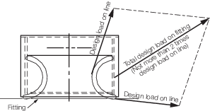
Figure 5.7.1 Design load applied to fittings
|