
Section
9 Structural requirements associated with towing and mooring
9.1 General
9.1.1 This Section applies to the design and construction of shipboard fittings
and supporting structures used for the normal towing and mooring operations. Normal
towing means towing operations necessary for manoeuvring in ports and sheltered
waters associated with the normal operations of the ship.
9.1.2 The arrangements, equipment and fittings of sufficient safe working load
are to be provided to enable the safe conduct of all towing and mooring operations
associated with the normal operations of the ship.
9.1.3 For ships, not subject to SOLAS Regulation II-1/3-4 Paragraph 1, but
intended to be fitted with equipment for towing by another ship or a tug, e.g. such
as to assist the ship in case of emergency as given in SOLAS Regulation II-1/3-4
Paragraph 2, the requirements designated as ‘other towing’ in this Section are to be
applied to the design and construction of those shipboard fittings and supporting
hull structures.
9.1.4 This Section is not applicable to the design and construction of
shipboard fittings and supporting hull structures used for special towing services
such as escort towing, canal transit towing, emergency towing for tankers etc. These
requirements are also not applicable to special purpose ships.
9.1.5 Shipboard fittings means bollards and bitts, fairleads, stand rollers,
chocks used for the normal mooring of the ship, and the similar components used for
normal or other towing of the ship. Any weld or bolt or equivalent device connecting
the shipboard fitting to the supporting structure is part of the shipboard fitting.
Other components such as capstans, winches, etc. are not covered by this Section.
9.1.6 Supporting hull structures means that part of the ship structure on/in
which the shipboard fitting is placed and which is directly submitted to the forces
exerted on the shipboard fitting. The supporting hull structure of capstans,
winches, etc. used for normal or other towing and mooring operations mentioned above
is also to comply with the requirements specified in this Section.
9.1.7 The nominal capacity condition is defined as the theoretical condition where the
maximum possible deck cargoes are included in the ship arrangement in their
respective positions. For container ships, the nominal capacity condition represents
the theoretical condition where the maximum possible number of containers is
included in the ship arrangement in their respective positions.
9.1.8 Ship Design Minimum Breaking Load (MBLSD) is the minimum breaking
load of new, dry mooring lines or tow line for which shipboard fittings and
supporting hull structures are designed in order to meet mooring restraint
requirements or the towing requirements of other towing service.
9.1.9 Line Design Break Force (LDBF) is the minimum force at which a new, dry,
spliced, mooring line will break at. This is applicable to all synthetic cordage
materials.
9.2 Towing
9.2.1 The strength of shipboard fittings used for normal towing operations at
bow, sides and stern and their supporting hull structures are to comply with the
requirements specified in this sub-Section. For fittings intended to be used for
both towing and mooring, Pt 3, Ch 13, 9.3 Mooring is also to be applied.
9.2.2 Where a ship is equipped with shipboard fittings intended to be used for other towing
services, the strength of these fittings and their supporting hull structures are
also to comply with the requirements specified.
9.2.3 Shipboard fittings for towing are to be located on stiffeners and/or girders which
are part of the deck construction so as to facilitate efficient distribution of the
towing load. Other arrangements are acceptable (for chocks in bulwarks, etc.),
provided that the strength is confirmed adequate for the intended service.
9.2.4 The design load applied to shipboard fittings and supporting hull
structure is not to be less than that given in Table 13.9.1 Minimum design load for deck fittings and supporting structure -
Towing.
Table 13.9.1 Minimum design load for deck fittings and supporting structure -
Towing
| Use/Item
|
Minimum
design load (see Notes 1 to 3)
|
| Normal towing
(harbour/manoeuvring)
|
1,25 times the
intended maximum towing load (e.g. static bollard pull ) as
indicated on the towing and mooring arrangements plan
|
| Other towing
service
(SOLAS Regulation II-1/3-4 Paragraph 2)
|
Ship design minimum breaking load given in Pt 3, Ch 13, 7.8 Towline and towing arrangement
|
|
For fittings intended to be used for both normal towing and other
towing service
|
The greater of the specified loads in each case
|
Note 1. When a safe
towing load TOW greater than that determined according to Pt 3, Ch 13, 9.2 Towing 9.2.12 is
requested, then the design load is to be increased in accordance
with the appropriate TOW/design load relationship given in this
sub-Section.
Note 2. Side
projected area including that of deck cargoes as given by the
ship nominal capacity condition is to be taken into account for
selection of towing lines and the loads applied to shipboard
fittings and supporting hull structures. The nominal capacity
condition is defined in Pt 3, Ch 13, 9.1 General 9.1.7.
Note 3. The increase
of the line design break force for synthetic ropes need not to
be taken into account for the loads applied to shipboard
fittings and supporting hull structures.
|
9.2.5 The design load is to be applied to fittings in all directions that
could occur by taking into account the arrangement shown on the towing and mooring
arrangements plan. Where the towing line takes a turn at a fitting, the total design
load applied to the fitting is equal to the resultant of the design loads acting on
the line, see
Figure 13.9.1 Design load applied to fittings.
However, in no case does the design load applied to the fitting need to be greater
than twice the design load on the line.
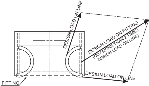
Figure 13.9.1 Design load applied to fittings
9.2.6 Shipboard fittings are to be selected from an acceptable National or International
standard and to be based on the following minimum loads.
9.2.7 Towing bitts (double bollards) are to be chosen for the towing line attached with an
eye splice if the industry standard distinguishes between different methods to
attach the line, i.e. figure-of eight or eye splice attachment.
9.2.8 When the shipboard fitting is not selected from an accepted industry
standard, the strength of the fitting based on net scantlings and its attachment to
the ship is to be adequate for the loads specified by the Table 13.9.1 Minimum design load for deck fittings and supporting structure -
Towing based on the acceptance criteria given in Pt 3, Ch 13, 9.2 Towing 9.2.10 or Pt 3, Ch 13, 9.2 Towing 9.2.11 as appropriate. The capability of the
structure to withstand buckling is also to be assessed. Towing bitts (double
bollards) are required to resist the loads caused by the towing line attached with
an eye splice. For strength assessment, beam theory or finite element analysis using
net scantlings is to be applied, as appropriate. Corrosion additions and wear down
allowance is to be added to the net scantlings as defined in this Section.
9.2.9 The net scantlings of the supporting hull structure for the fittings are
to be adequate for the loads specified by the Table 13.9.1 Minimum design load for deck fittings and supporting structure -
Towing based on the acceptance criteria given in by Pt 3, Ch 13, 9.2 Towing 9.2.10 or Pt 3, Ch 13, 9.2 Towing 9.2.11 as appropriate. The capability of the
structure to withstand buckling is also to be assessed. The reinforced members
beneath shipboard fittings are to be effectively arranged for any variation of
direction (horizontally and vertically) of the towing forces acting upon the
shipboard fittings, see
Figure 13.9.2 Supporting hull structure for a sample arrangement. Proper alignment of the fitting and
its supporting hull structure is to be ensured. The acting point of the towing force
on a shipboard fitting is to be taken at the attachment point of a towing line or at
a change in its direction. For bollards and bitts the attachment point of the towing
line is to be taken not less than 4/5 of the tube height above the base as indicated
in Figure 13.9.2 Supporting hull structure. Corrosion additions are to be added to the net scantlings as
defined in this Section.
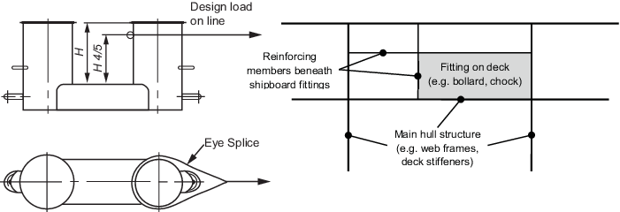
Figure 13.9.2 Supporting hull structure
9.2.11 For strength assessment by means of finite element analysis the mesh is
to be fine enough to represent the geometry as realistically as possible. The aspect
ratios of elements are not to exceed 3. Girders are to be modelled using shell or
plane stress elements. Symmetric girder flanges may be modelled by beam or truss
elements. The element height of girder webs must not exceed one-third of the web
height. In way of small openings in girder webs the web thickness is to be reduced
to an appropriate mean thickness over the web height. Large openings are to be
modelled. Stiffeners may be modelled using shell or plane stress elements. The mesh
size of stiffeners is to be fine enough to obtain proper bending stress. If flat
bars are modelled using shell or plane stress elements, then dummy rod elements are
to be modelled at the free edge of the flat bars and the stresses of the dummy
elements are to be evaluated. Stresses are to be read from the centre of the
individual element. For shell elements the stresses are to be evaluated at the mid
plane of the element. The Von Mises stress within the supporting structure of
fittings, calculated with net scantlings, is not to exceed the specified minimum
yield strength of the material.
Table 13.9.2 Allowable stress within the
supporting structure of shipboard fittings
|
|
Normal stress, in
N/mm2
|
Shear stress, in
N/mm2
|
| Allowable stress
|

|

|
| where

σ0
= specified minimum yield strength of the material in
N/mm2
Note Normal stress is
defined as the sum of bending and axial stresses. No stress
concentration factors accounted for and as such may need to be
considered separately.
|
9.2.13 TOW, in tonnes, of each shipboard fitting is to be marked (by weld bead
or equivalent) on the deck fittings used for towing. For fittings intended to be
used for both, towing and mooring, SWL, in tonnes, according to Pt 3, Ch 13, 9.3 Mooring is to be marked in addition to
TOW.
9.2.14 The above requirements on TOW apply for the use with no more than one towline line.
If not otherwise chosen, for towing bitts (double bollards) TOW is the load limit
for a towing line attached with an eye-splice.
9.3 Mooring
9.3.1 The strength of shipboard fittings used for mooring operations and their
supporting hull structures as well as the strength of supporting hull structures of
winches and capstans are to comply with the requirements specified in this
sub-Section. For fittings intended to be used for both mooring and towing, Pt 3, Ch 13, 9.2 Towing is also to be applied.
9.3.2 Shipboard fittings, winches and capstans for mooring are to be located on stiffeners
and/or girders which are part of the deck construction so as to facilitate efficient
distribution of the mooring load. Other arrangements are acceptable (for chocks in
bulwarks, etc.) provided that the strength is confirmed adequate for the service.
9.3.4 The design load is to be applied to fittings in all directions that
could occur by taking into account the arrangement shown on the towing and mooring
arrangements plan. Where the mooring line takes a turn at a fitting, the total
design load applied to the fitting is equal to the resultant of the design loads
acting on the line, see
Figure 13.9.1 Design load applied to fittings. However, in no
case does the design load applied to the fitting need to be greater than twice the
design load on the line.
Table 13.9.3 Minimum design load for deck fittings and supporting structure -
Mooring
| Use/Item
|
Minimum design load (see
Notes 1 to 3)
|
| Moorings
(Fittings and their supporting hull structure)
|
1,15 times the ship design
minimum breaking load given in Pt 3, Ch 13, 7.5 Mooring lines (Equipment Number ≤ 2000) or Pt 3, Ch 13, 7.6 Mooring lines (Equipment Number > 2000) as appropriate.
|
| Winches
(Supporting hull structure only)
|
1,25 times the intended
maximum brake holding load, where the maximum brake holding load is
to be assumed not less than 80% of the ship design minimum breaking
load given in Pt 3, Ch 13, 7.5 Mooring lines (Equipment Number ≤ 2000) or Pt 3, Ch 13, 7.6 Mooring lines (Equipment Number > 2000) as appropriate.
|
| Capstans
(Supporting hull structure only)
|
1,25 times the maximum hauling
in force, where hauling in force is defined as the maximum pull of
the capstan or 1,25 times the intended maximum brake holding load if
that be greater.
|
Note 1. When a safe
working load SWL greater than that determined according to the
Rules is requested, the design load is to be increased in
accordance with the appropriate SWL/design load relationship
given in Pt 3, Ch 13, 9.3 Mooring 9.3.12.
Note 2. Side
projected area including that of deck cargoes as given by the
ship nominal capacity condition is to be taken into account for
the selection of mooring lines and the loads applied to
shipboard fittings and supporting hull structure. The nominal
capacity condition is defined in Pt 3, Ch 13, 9.1 General 9.1.7.
Note 3. The increase
of the line design break force for synthetic ropes need not to
be taken into account for the loads applied to shipboard
fittings and supporting hull structures.
|
9.3.6 Mooring bitts (double bollards) are to be chosen for the mooring line
attached in figure-of-eight fashion if the industry standard distinguishes between
different methods to attach the line, i.e. figure-of-eight or eye-splice attachment.
With the line attached to a mooring bitt in the usual way (figure-of-eight fashion),
either of the two posts of the mooring bitt can be subjected to a force twice as
large as that acting on the mooring line. Disregarding this effect, depending on the
applied industry standard and fitting size, overload may occur.
9.3.7 When the shipboard fitting is not selected from an accepted industry
standard, the strength of the fitting based on net scantlings and its attachment to
the ship is to be adequate for the loads specified in Table 13.9.3 Minimum design load for deck fittings and supporting structure -
Mooring based on the acceptance
criteria given in Pt 3, Ch 13, 9.3 Mooring 9.3.10 or Pt 3, Ch 13, 9.3 Mooring 9.3.11 as appropriate. The capability of the
structure to withstand buckling is also to be assessed. Mooring bitts (double
bollards) are required to resist the loads caused by the mooring line attached in
figure-of-eight fashion. For strength assessment, beam theory or finite element
analysis using net scantlings is to be applied, as appropriate. Corrosion additions
and wear down allowance is to be added as defined in this Section.
9.3.8 The net scantlings of the supporting hull structure for the fittings are
to be adequate for the loads given in Table 13.9.3 Minimum design load for deck fittings and supporting structure -
Mooring based on the acceptance
criteria given in Pt 3, Ch 13, 9.3 Mooring 9.3.10 or Pt 3, Ch 13, 9.3 Mooring 9.3.11 as appropriate. The capability of the
structure to withstand buckling is also to be assessed. The arrangement of
reinforced members beneath shipboard fittings, winches and capstans is to consider
any variation of direction (horizontally and vertically) of the mooring forces
acting upon the shipboard fittings, see
Figure 13.9.3 Supporting hull structure for a sample arrangement. Proper alignment of fitting and
supporting hull structure is to be ensured. The acting point of the mooring force on
shipboard fittings is to be taken at the attachment point of a mooring line or at a
change in its direction. Corrosion additions are to be added to the net scantlings
as defined in this Section.
9.3.9 For bollards and bitts the attachment point of the mooring line is to be
taken not less than 4/5 of the tube height above the base, see
Figure 13.9.3 Supporting hull structure.
However, if fins are fitted to the bollard tubes to keep the mooring line as low as
possible, then the attachment point of the mooring line is to be taken at the
location of the fins, see
Figure 13.9.3 Supporting hull structure.
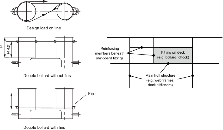
Figure 13.9.3 Supporting hull structure
9.3.11 For strength assessment by means of finite element analysis the mesh is
to be fine enough to represent the geometry as realistically as possible. The aspect
ratios of elements are not to exceed 3. Girders are to be modelled using shell or
plane stress elements. Symmetric girder flanges may be modelled by beam or truss
elements. The element height of girder webs must not exceed one-third of the web
height. In way of small openings in girder webs the web thickness is to be reduced
to an appropriate mean thickness over the web height. Large openings are to be
modelled. Stiffeners may be modelled using shell or plane stress elements. The mesh
size of stiffeners is to be fine enough to obtain proper bending stress. If flat
bars are modelled using shell or plane stress elements, then dummy rod elements are
to be modelled at the free edge of the flat bars and the stresses of the dummy
elements are to be evaluated. Stresses are to be read from the centre of the
individual element. For shell elements the stresses are to be evaluated at the mid
plane of the element. The Von Mises stress within the supporting structure of
fittings, calculated with net scantlings, is not to exceed the specified minimum
yield strength of the material.
9.3.13 The SWL, in tonnes, of each shipboard fitting is to be marked (by weld
bead or equivalent) on the deck fittings used for mooring. For fittings intended to
be used for both, mooring and towing, the TOW, in tonnes, according to Pt 3, Ch 13, 9.2 Towing is to be marked in addition to the
SWL.
9.3.14 The above requirements on SWL apply for the use with no more than one mooring line.
9.4 Towing and mooring arrangements plan
9.4.1 The SWL and TOW for the intended use for each shipboard fitting is to be
noted in the towing and mooring arrangements plan available on board for the
guidance of the Master. It is to be noted that TOW is the load limit for towing
purpose and SWL that for mooring purpose. If not otherwise chosen, for towing bitts
it is to be noted that TOW is the load limit for a towing line attached with an eye
splice.
9.4.2 Information provided on the plan is to include in respect for each
shipboard fitting:
- location on the ship;
- fitting type;
- SWL/TOW;
- purpose (mooring/harbour towing/other towing); and
- manner of applying towing or mooring line load,
including limiting fleet angle, i.e. angle of change in direction of a line
at the fitting.
Furthermore, information provided on the plan is to include:
Note Item (c) with respect to items (d)
and (e), is subject to approval.
- the arrangement of mooring lines showing number of lines
(N);
- the ship design minimum breaking load
(MBLSD, MBLSD* or
MBLSD** as appropriate) and;
- the acceptable environmental conditions, , the minimum
environmental conditions are as given in Pt 3, Ch 13, 7.6 Mooring lines (Equipment Number > 2000) for the recommended ship design minimum breaking load
for ships with EN > 2000:
- 30 second mean wind speed from any direction
(Vw or
 ) )
- Maximum current speed acting on bow or stern
(±10°).
9.5 Corrosion addition
9.5.1 For ships other than double hull oil tankers and bulk carriers with a CSR
notation ( see
Pt 1, Ch 2, 2.3 Class notations (hull)), an allowance for
corrosion is to be added to the net thickness derived as indicated below:
- For the supporting hull structure, a corrosion addition
of 2 mm is to be added to the net thickness derived.
- For pedestals and foundations on deck which are not part
of a fitting according to an accepted industry standard, 2,0 mm.
- For shipboard fittings not selected from an accepted
industry standard, 2,0 mm.
9.5.2 For double hull oil tankers and bulk carriers with a CSR notation
(see
Pt 1, Ch 2, 2.3 Class notations (hull)),
corrosion addition for the hull supporting structure is to be in accordance with
IACS Common Structural Rules for Bulk Carriers and Oil Tankers.
9.6 Wear allowance
9.6.1 In addition to the corrosion addition given in Pt 3, Ch 13, 9.5 Corrosion addition, the wear allowance,
tw, for shipboard fittings that are not selected from an
acceptable National or International standard, is not to be less than 1,0 mm, added
to surfaces which are intended to regularly contact the line.
|