
Section
1 General
1.1 Application
1.1.1 All cargo ships, regardless of tonnage, except those engaged solely in the
carriage of either liquid or solid bulk cargoes, are to be provided with a Cargo
Securing Manual approved by the Flag Administration, as required by SOLAS 1974 (as
amended). Pt 3, Ch 14, 2 Fixed cargo securing fittings, materials and testing, Pt 3, Ch 14, 4 Ship structure, Pt 3, Ch 14, 7 Container securing arrangements for stowage using cell guides (if applicable) and Pt 3, Ch 14, 10 Surveys apply to all ships for which a Cargo Securing Manual is required.
It is recommended that the container securing arrangements in the Cargo Securing Manual
be designed in accordance with Pt 3, Ch 14, 3 Loose container securing fittings, materials and testing , Pt 3, Ch 14, 5 Container securing arrangements for stowage on exposed decks without cell guides, Pt 3, Ch 14, 6 Container securing arrangements for underdeck stowage without cell guides, Pt 3, Ch 14, 8 Determination of forces for container securing arrangements and Pt 3, Ch 14, 9 Strength of container securing arrangements. Furthermore, it is recommended that the container securing
arrangements be submitted to Lloyd’s Register (hereinafter referred to as LR), for
formal approval. In cases where LR is authorised to carry out the approval of the Cargo
Securing Manual on behalf of a National Administration and the container securing
arrangements have not been designed on the basis of the LR Rules nor received formal LR
approval, the Cargo Securing Manual will be annotated accordingly, highlighting this
fact. In general, Cargo Securing Manuals can be approved by LR if authorised by the
National Authority.
1.1.2 Fixed
fittings which are part of the container lashing equipment or which
may affect the strength of the ship’s hull are subject to approval
on the basis of the requirements of this Chapter. Details of the connection
and the supporting ship structure require approval to satisfy the
design loads determined in accordance with Pt 3, Ch 14, 8 Determination of forces for container securing arrangements or the safe working load of the fixed fitting, as
applicable. Drawings are to be submitted showing details of the fittings,
the attachment, the local foundations and information about the intended
materials and welding.
1.1.3 The
requirements for container securing arrangements have been framed
in relation to ISO Standard Series 1 ISO 1496-1:1990, including Amendment
Nos. 1, 2 and 3, Freight Containers. For previous ISO 1496-1:1984
containers, reference should be made to the July 2008 LR Rules. Proposals
to consider higher allowable forces in accordance with ISO 1496-1,
including Amendment No. 4, 2006, will be specially considered. Proposals
for the securing of other types of containers will be specially considered.
1.1.4 Containers
are to be loaded so as not to exceed the weights and distribution
within the stack according to the Cargo Securing Manual (CSM). The
permissible loading patterns are to be clearly indicated on the Container
Securing Arrangement Plan carried on board the ship.
1.1.5 Containers
may be approved and certified using LR’s Container Certification
Scheme.
1.1.6 Where
it is intended and specified that loose or fixed parts of the container
securing system are used for lifting appliance purposes, e.g. pedestal
sockets and fittings used for lifting of hatch covers, or twistlocks
used for vertical tandem lifting, the requirements of LR’s Code for Lifting Appliances in a Marine Environment, July 2022 are
applicable. If no approval from lifting aspects is sought, the devices
will be considered as part of a container securing arrangement only.
1.1.7 For ships having the class notation Container Ship, an effective
breakwater is to be fitted to protect the containers against green sea impact loads. For
other ships which are equipped for the carriage of containers on deck, protection of the
cargo is recommended by the provision of a breakwater. See also
Pt 3, Ch 14, 8.2 Ship motion, wind and green sea forces acting on containers.
1.1.8 Forward
of 0,75L, it is recommended that all door ends face aft
in order to improve the performance of the container walls to withstand
green sea loads.
1.1.9 Improper
ship handling related to course and speed or threshold phenomena like
parametric rolling can create adverse forces acting on the ship and
the cargo which are in excess of the forces determined on the basis
of Section Pt 3, Ch 14, 8 Determination of forces for container securing arrangements. It is the responsibility
of the Master to apply good seamanship in order to mitigate excessive
ship motions to reduce forces acting on the cargo stowage arrangements.
1.2 Classification notations and descriptive notes
1.2.1 Ships
with container securing arrangements which are designed and constructed
in accordance with this Chapter will be eligible to be assigned the
special features notation CCSA (certified container securing
arrangements). In addition to the fixed fittings, the Initial and
Periodical Survey requirements of Section Pt 3, Ch 14, 10 Surveys for all loose fittings are applicable. Where loose container
securing fittings are supplied for part container stowage only, the
special features notation will be suitably modified.
1.2.2 Ships
with container securing arrangements which are designed and constructed
in accordance with this Chapter, but where the Initial and Periodical
Survey requirements for loose fittings in Section Pt 3, Ch 14, 10 Surveys are not requested, will be eligible
to be assigned the descriptive note CSA (container securing
arrangement) and for an entry to be made in column 6 of the Register
Book.
1.2.3 On container ships an approved onboard lashing program to calculate forces
acting on the container stowage arrangement is to be provided, complying with this
chapter. This may be an extension to the loading instrument covered under Pt 3, Ch 4, 8.3 Loading instrument.
The ship will be eligible to be assigned the special features notation BoxMax,
with one or more of the supplementary letters V and W. The notation
BoxMax(V,W) may be supplemented with the letter L if the conditions for
this notation are satisfied. BoxMax may be supplemented with the letter M
if the conditions for this notation are satisfied..
1.2.4 Special consideration may be given to waiving the requirement for an onboard
lashing program as required by Pt 3, Ch 4, 8.4 Onboard lashing program 8.4.1 and e.g. For smaller
container ships where the container securing arrangements are relatively
straightforward.
1.2.5 It
is a prerequisite for assignment of the special features notation BoxMax that the container securing arrangements in the Cargo Securing
Manual are designed in accordance with this Chapter and submitted
to Lloyd’s Register for formal approval.
1.2.6 The container securing arrangements of a container ship may take into
account specific voyage routes and seasons, provided the ship has been assigned the
special features notation BoxMax with one of the following supplementary letter
sequences: V or V,W or V,W,L or M. The features offered by
these supplementary letter sequences are defined in Table 14.1.1 BoxMax notation features .
1.2.7 The onboard lashing program is to be capable of performing calculations
specific to defined sea areas and seasons, and the weather dependent factors for these
areas and seasons have been supplied by LR.
- If the weather dependent factors have been supplied by LR for specific
sea areas, the ship will be eligible to be assigned the special features notation
BoxMax(V).
- If the factors have been supplied by LR for specific sea areas in combination with
seasons, the ship will be eligible to be assigned the special features notation
BoxMax(V,W).
- If the factors have been supplied by LR for limited voyages, the
ship will be eligible to be assigned the special features notation
BoxMax(V,W,L).
- If the factors have been supplied by LR for ship motions and
environmental conditions, the ship will be eligible to be assigned the special
features notation BoxMax(M).
See also
Pt 3, Ch 4, 8.4 Onboard lashing program.
1.2.9 A ship designed to carry containers that is provided with safe access and
securing arrangements in accordance with the Rules for Ergonomic Container Lashing, July 2022 will
be eligible to be assigned the special features notation ECL (Ergonomic Container
Lashing), with supplementary descriptor.
Table 14.1.1 BoxMax notation features
| Notation
|
Additional feature description
|
| BoxMax(V)
|
V: Voyage dependencies
The assessment of the loads
acting on the containers and the container securing arrangements may take
account of the areas on the trading route of the ship. The North Atlantic
represents one of the most severe weather areas in the world. For other
areas the weather conditions may be less severe, and hence the assignment
of the BoxMax(V) notation allows weather dependent factors to be
applied to the environmental (dynamic) loads acting on the container
stacks in-hold or on-deck.
For the V feature,
the weather dependent factors are determined on the basis of the annual
environmental wave data, see Note 1.
The
weather dependent factors applicable to annual environmental wave data
for the requested sea areas will be supplied by LR, see Note
2.
|
| BoxMax(V,W)
|
W: Weather dependency (Season dependency)
The
BoxMax(V,W) notation allows the change in weather conditions
for various seasons to be taken into account for the assessment of the
environmental loads acting on container stacks in-hold or on-deck. For
example, this allows enhanced flexibility for the carriage of containers
in the summer season, when the weather conditions are usually less severe
than in the winter months.
For the W feature,
the weather dependent factors are determined on the basis of the seasonal
environmental wave data.
The weather dependent factors applicable to
seasonal environmental wave data for the requested sea areas will be
supplied by LR, see Note 2.
|
| BoxMax(V,W,L)
|
L:
Limited duration voyages
The BoxMax(V,W,L) notation
potentially allows increased flexibility for the carriage of containers
on board the ship for limited duration voyages. When applying the
L feature, limited duration voyage factors are applicable for
voyages of less than 48 hours. They are suitable for short coastal
voyages, for example between ports such as Hamburg and Rotterdam or
between Hong Kong and Xiamen (China). Typically it will allow enhanced
flexibility for the carriage of containers and may allow reduced lashing
requirements between local ports.
The process of
application of the BoxMax(V,W,L) limited duration voyage feature
is given in Pt 3, Ch 14, 1.3 Application of the BoxMax(V,W,L) notation.
The weather dependent factors applicable to limited
duration voyages based on wave heights predicted by weather forecasts
will be supplied by LR.
|
| BoxMax(M)
|
M:
Ship motion monitoring
The BoxMax(M) notation allows maximum
flexibility in the way containers are carried for any voyage. The degree
of lashing can be fully appropriate to operation, see Note
3.
The Master will be required to manage the motion of the ship
during the voyage by good seamanship and by weather routing, and not
exceed the declared ship motions.
The maximum motion of the ship
during the voyage is to be recorded and compared to the declared ship
motion.
The process of application of the BoxMax(M) ship
motion monitoring feature is given in Pt 3, Ch 14, 1.4 Application of the BoxMax(M) notation.
|
|
Note 2: LR will supply
weather dependent factors applicable to the list of sea areas requested
by the owner. The requested sea areas must cover the whole of the voyage
route to be used. If the vessel sails outside of the requested sea areas
then all the weather dependent factors should be set to 1,0.
Note 3: LR will supply weather dependent factors in the form of a look up
table specific to the ship; the voyage factors shall be selected based on
the maximum ship motion being declared.
|
1.3 Application of the BoxMax(V,W,L) notation
1.3.1 The BoxMax(V,W,L) notation requires the following process to be applied by the
Ship’s Master.
1.3.2 For the limited duration voyage feature to be applicable the following process must
be in place:
- The ship must subscribe to an ocean weather forecast service provided by a
recognised and reputable met ocean weather forecasting organisation. The
forecast is to include wind speed and wave heights for a minimum period of 5
days and preferably 10 days. The responsibility for selection of the weather
forecasting organisation lies with the Master.
- The limited voyage feature shall not hazard safe navigation and
adverse weather conditions should be avoided as far as possible.
1.3.3 The limited duration voyage feature can only be applied in the following
scenarios:
- The maximum length of a limited duration voyage is 48 hours in Open Water. A
limited duration voyage may be slightly extended at the Master’s discretion
provided the forecast is favourable. Voyages longer than this will need to
be considered using the BoxMax(V,W) approaches.
- There should be no warnings for major storms with maximum sustained winds of
more than 119 km per hour for an area within 500 miles from the long-range
weather forecast.
where:
| Open Water
|
May be taken as starting at the outer harbour limits or harbour
breakwater, as applicable. The concept of Open Water here is used to
define the point at which the ship will leave the confines of the
port and any estuaries or inshore navigation confines.
|
| Tdepart
|
Is to be taken as the estimated time in hours after the initial
forecast that the ship enters Open Water after leaving the port of
departure.
|
| Tarrive
|
Is to be taken as the estimated time in hours after the initial
forecast that the ship leaves Open Water prior to entering the port
of arrival.
|
1.3.4 The supplied weather dependent factors applicable to limited duration voyages are
based on the significant wave height.
1.3.5 The Master needs to select the appropriate significant wave height for the limited
duration voyage, HSL. The significant wave height for the limited
duration voyage is to be rounded up to the next integer and is to be selected as follows:
|
HSL |
= |
Hforecast if the
Tarrive is less than 72 hours after the time of
the initial forecast. |
| = |
Hforecast + 1 m if the
Tarrive is more than 72 hours after the time of
the initial forecast. |
| = |
Hforecast + 2 m if the
Tarrive is more than 96 hours after the time of
the initial forecast.
where
Hforecast is the maximum significant wave
height predicted for the limited duration voyage. It is to be
extracted from the forecast at the time of planning the cargo
stowage up to the time when the vessel leaves Open Water prior to
entering the port of arrival. The forecast period is not to be less
than 5 days.
|
The time of the initial forecast is to be taken as the most recent forecast prior to
commencement of cargo planning operations.
1.3.6 When the ship departs, if the latest forecast is more severe than the
earlier forecasts, then is to be taken as the maximum significant wave height from
the latest forecast for the period up to the time the ship leaves Open Water prior
to entering the port of arrival +24 hours for the planned voyage, if this exceeds
from Pt 3, Ch 14, 1.3 Application of the BoxMax(V,W,L) notation 1.3.5.
1.3.7 The significant wave height used for the limited duration voyage should be recorded
in the cargo plan information and the onboard lashing computer for the voyage. The
ship specific weather dependent coefficients for a range of significant wave heights
will be provided by Clasifications Register as part of the BoxMax(V,W,L)
notation.
1.3.8 Example of application of BoxMax(V,W,L):
Scenario 1
|
|
|
|
|
|
Date
|
14 July
|
15 July
|
16 July
|
17 July
|
18 July
|
19 July
|
|
|
|
Voyage schedule
|
Planning commences at 14:00
|
|
|
Stowage and lashing
Leaves quayside At
13:00
Enters Open Water at 16:00
|
Voyage 18 hours
Leaves Open Water at 10:00
Arrive at quayside
|
|
|
|
|
Forecast day 14 July @ 12:00
– initial forecast
|
|
|
|
Forecast time
|
12:00
|
|
|
|
|
|
|
|
|
Time from initial forecast
|
|
|
|
T
depart = 76 hrs
|
T
arrive = 94 hrs
|
|
|
|
|
Forecast wave height
|
3,3 m
|
3,3 m
|
3,7 m
|
3,7 m
|
3,5 m
|
3,5 m
|
|
|
|
Hforecast
|
3,7 m
|
|
|
|
ΔHforecast
(Tarrive>72h)
(Tarrive<96h)
|
1,0 m
|
|
|
|
Limited duration HSL
|
3,7 m + 1,0 m = 4,7 m
rounded up to the next integer = 5 m
|
|
|
|
Action
|
Plan lashing requirement with
HSL = 5 m
|
|
|
|
Forecast day 15 July @ 12:00
|
|
|
|
Forecast time
|
-
|
12:00
|
|
|
|
|
|
|
|
Forecast wave height
|
-
|
3,5 m
|
3,7 m
|
3,5 m
|
3,3 m
|
3,2 m
|
|
|
|
Action
|
-
|
Monitor weather forecast –
no change in wave height expected
|
|
|
|
Forecast day 16 July @ 12:00
|
|
|
|
Forecast time
|
-
|
-
|
12:00
|
|
|
|
|
|
|
Forecast wave height
|
-
|
-
|
3,7 m
|
3,7 m
|
3,5 m
|
3,3 m
|
|
|
|
Action
|
-
|
-
|
Monitor weather forecast –
no change in wave height expected
|
|
|
|
Forecast day 17 July @ 12:00
|
|
|
|
Forecast time
|
-
|
-
|
-
|
12:00
|
|
|
|
|
|
Forecast wave height
|
-
|
-
|
-
|
3,8 m
|
4,1 m
|
4,0 m
|
|
|
|
Action
|
-
|
-
|
-
|
Max forecast wave height
increased to 4,1 m.
4,1 m is less than planning wave
height of 5,0 m
Voyage can be
undertaken.
Monitor latest forecast and
actual sea state
|
|
|
|
Forecast day 18 July @ 12:00
|
|
|
|
Forecast time
|
-
|
-
|
-
|
-
|
12:00
|
|
|
|
|
Forecast wave height
|
-
|
-
|
-
|
-
|
4,2 m
|
4,0 m
|
|
|
|
Action
|
-
|
-
|
-
|
Monitor latest forecast and
actual sea state
|
|
|
|
|
|
Scenario 2
|
|
|
|
|
|
Date
|
14 July
|
15 July
|
16 July
|
17 July
|
18 July
|
19 July
|
|
|
|
Voyage schedule
|
Planning commences at 14:00
|
|
|
Stowage and lashing
Leaves quayside At
13:00
Enters Open Water at 16:00
|
Voyage 18 hours
Leaves Open Water at 10:00
Arrive at quayside
|
|
|
|
|
Forecast day 14
July @ 12:00 – initial forecast
|
|
|
|
Forecast time
|
12:00
|
|
|
|
|
|
|
|
|
Time from initial forecast
|
|
|
|
T
depart = 76 hrs
|
T
arrive = 94 hrs
|
|
|
|
|
Forecast wave height
|
3,3 m
|
3,3 m
|
3,7 m
|
3,7 m
|
3,5 m
|
3,3 m
|
|
|
|
Hforecast
|
3,7 m
|
|
|
|
ΔHforecast
(Tarrive>72h)
(Tarrive<96h)
|
1,0 m
|
|
|
|
Limited duration HSL
|
3,7 m + 1,0 m = 4,7 m rounded up to the
next integer = 5 m
|
|
|
|
Action
|
Plan lashing requirement with
HSL = 5 m
|
|
|
|
Forecast day 15
July @ 12:00
|
|
|
|
Forecast time
|
-
|
12:00
|
|
|
|
|
|
|
|
Forecast wave height
|
-
|
3,5 m
|
3,7 m
|
3,7 m
|
3,5 m
|
3,8 m
|
|
|
|
Action
|
-
|
Monitor weather
forecast
|
|
|
|
Forecast day 16
July @ 12:00
|
|
|
|
Forecast time
|
-
|
-
|
12:00
|
|
|
|
|
|
|
Forecast wave height
|
-
|
-
|
3,7 m
|
3,7 m
|
4,4 m
|
4,5 m
|
|
|
|
Action
|
-
|
-
|
Forecast indicates increasing waveheight
(Maximum wave height still below HSL of 5 m)
Consider reassessing lashing requirement with increased waveheight.
Monitor weather forecast
|
|
|
|
Forecast day 17
July @ 12:00
|
|
|
|
Forecast time
|
-
|
-
|
-
|
12:00
|
|
|
|
|
|
Forecast wave height
|
-
|
-
|
-
|
4,8 m
|
5,5 m
|
5,4 m
|
|
|
|
Action
|
-
|
-
|
-
|
Final forecast from
Tdepart to Tarrive + 24
hours is higher than HSL, hence cargo plan needs
to be reassessed. Master needs to select an appropriate
HSL value, e.g. 6 m. Might result in delay to
planned departure.
|
|
|
|
Forecast day 18
July @ 12:00
|
|
|
|
Forecast time
|
-
|
-
|
-
|
-
|
12:00
|
|
|
|
|
Forecast wave height
|
-
|
-
|
-
|
-
|
5,5 m
|
5,4 m
|
|
|
|
Action
|
-
|
-
|
-
|
-
|
Monitor latest forecast and
actual sea state
|
|
|
|
|
|
1.4 Application of the BoxMax(M) notation
1.4.1 The BoxMax(M) notation requires the following process to be applied by the
Ship’s Master.
1.4.2 For the ship motion monitoring notation to be applicable the following process must
be in place:
- At the start of a voyage, the Master shall declare the
maximum expected ship motions and environmental conditions and assign weather
dependent factors accordingly. The responsibility for selection of appropriate
ship motions and environmental conditions lies with the Master.
- The ship motion monitoring feature shall not hazard safe
navigation and adverse weather conditions should be avoided as far as
possible.
1.4.3 The supplied weather dependent factors applicable to ship motion notation are based
on the declared ship motion and environmental conditions.
1.4.4 The maximum ship motion, environmental conditions and weather dependent factors
planned for the voyage should be recorded in the cargo plan information and the
onboard lashing computer for the voyage. The ship specific weather dependent
coefficients for a range of ship motion and environmental conditions will be
provided by LR as part of the BoxMax(M) notation.
1.4.5 LR can provide ship specific guidance with regard to voyage ship motion predictions
and environmental loading.
1.5 Plans and information required
1.5.1 For
all fixed cargo securing arrangements, except container securing arrangements,
the following information and plans are to be submitted:
-
Details of certification
including safe working load (SWL) of fixed cargo securing fittings.
-
Plans of structure
in way of fixed cargo securing fittings.
-
Direction of
loads imposed on the ship’s fixed cargo securing fittings.
-
A general arrangement
of fixed cargo securing fittings.
1.5.2 For
container securing arrangements, the following plans and information
are to be submitted:
- General arrangement plan showing the disposition and design weights of
the containers.
- Rule length.
- Details of materials, stiffness and scantling of lashing bridges
including heights from base line, heights of bottom of bridge, heights of each tier.
- Details of green water protection including longitudinal,
transverse and vertical extents.
- Details of materials, design, scantlings of cell guides
structure, pedestals, and other container securing arrangements, where fitted.
- Details of certification, including safe working load
(SWL), of fixed and loose container securing fittings.
- Details of twistlock height and separation clearances.
- Details of stacking cones and their arrangements in holds.
- Details of lashing rod diameters and dimensions in x, y and z
directions.
- Plans of structure in way of fixed container securing
fittings and arrangements.
- Design values of the following ship parameters for the
container load departure and arrival conditions:
- Moulded draught (T
c)
- Transverse metacentric height
(GM).
- Cargo Securing Manual, see
Pt 3, Ch 14, 1.5 Plans and information required 1.5.3.
1.5.3 The Cargo Securing Manual is to include the following information:
- For vessels with an approved onboard lashing program,
representative lashing calculations based on one design GM value within the
following range:
- A lower design GM value of 2,5 per cent of the
breadth B.
- An upper design GM value of 7,5 per cent of
B for ships with a breadth less than 52 m and 10 per cent of
B for ships where B ≥ 52 m.
- For vessels without an approved onboard lashing program,
representative lashing calculations based on design GM values as follows:
- A lower design GM value of 2,5 per cent of the
breadth B.
- An upper design GM value of 7,5 per cent of
B for ships with a breadth less than 52 m and 10 per cent of
B for ships where B >= 52 m.
- Actual GM values of the ship in the container loaded
condition from the approved Trim and Stability Booklet or Loading Manual
when the actual design GM values are outside the range specified in i) and
ii).
- For vessels with notation BoxMax(V), BoxMax(V,W),
BoxMax(V,W,L) or BoxMax(M) representative calculations based on
applicable weather reduction factors are to be included in the Cargo Securing
Manual.
1.5.4 Where
containers of types other than ISO containers are to be incorporated
in the stowage arrangement, the Cargo Securing Manual is to indicate
clearly the locations where these containers are stowed. The manual
is also to indicate the container weights and required securing arrangements
for stacks composed entirely of ISO Standard containers.
1.6 Securing systems
1.6.1 Containers
are to be secured by one, or a combination, of the following systems:
- Corner locking devices.
- Rod, wire or chain lashings.
- Buttresses, shores or equivalent structural restraint.
- Cell guides.
Alternative systems will be considered on the basis of their
suitability for the intended purpose.
1.6.2 Dunnage
is not to be used in association with approved container securing
systems except where forming part of an approved line load stowage,
see Pt 3, Ch 14, 5.5 Line Load stowage.
1.7 Symbols and definitions
1.7.1 The following definitions are applicable to this Chapter, except where
otherwise stated:
|
a
|
= |
breadth of the container, in metres (for longitudinally stowed
containers) |
|
b
|
= |
length of the container, in metres (for longitudinally stowed
containers) |
|
ci
|
= |
height of container i, in metres |
|
di
|
= |
flange thickness of container securing device (e.g. twistlock) below
container i, in metres |
|
a0
|
= |
acceleration parameter |
|
|
= |

|
|
asurge
|
= |
longitudinal acceleration due to surge, in m/s2
|
|
asway
|
= |
transverse acceleration due to sway, in m/s2
|
|
aheave
|
= |
vertical acceleration due to heave, in m/s2
|
|
aroll
|
= |
roll acceleration at the centre of motion of the vessel, in
rad/s2
|
|
|
= |
0,69 
|
|
apitch
|
= |
acceleration due to pitch, in rad/s2
|
|
Tp
|
= |
period of pitch of the ship, in seconds |
| = |
|
where
|
C1 |
= |
0,95 for Motion Case 1 |
| = |
0,52 for all other Motion Cases |
|
Tr
|
= |
period of roll of the ship, in seconds |
| = |
|
|
φ |
= |
design roll angle for container securing arrangements, in
degrees |
| = |
fHsRφf but not less than 12 degrees |
where
|
φf |
= |
55fBKe
(– 0,025B) but need not be taken greater than 30 degrees |
If φf is less than φm:
|
φf |
= |
55fgmfVfBKe(-0,025B)
but is not to be taken greater than φm |
where
φm the minimum unrestricted roll angle, in degrees, is to be taken as:
For ships with a breadth greater than 58 m:
|
|
= |
22 degrees for GM values below 7,5 per cent of the breadth,
B |
| = |
18 degrees for GM values above 10 per cent of the breadth,
B
for GM values between 7,5 and 10 per cent of the breadth,
B, the minimum unrestricted roll angle is to be determined by
linear interpolation.
|
For ships with a breadth less than 54 m
For ships with breadth, B, between 54 m and 58 m, the minimum unrestricted roll
angle is to be determined by linear interpolation.
|
fv |
= |
is to be taken as 1,0 |
|
fgm |
= |
 but is not to be taken less than 1,0 but is not to be taken less than 1,0 |
Note The calculations assume that the
Master takes action to avoid synchronous rolling and parametric rolling. LR can provide
ship specific guidance with regard to synchronous rolling and parametric rolling.
|
Ψ |
= |
design pitch angle, in degrees, |
| = |

|
but need not exceed 8°
|
e
|
= |
base of natural logarithms |
| = |
2,7183 |
|
fap
|
= |
hull form coefficient |
| = |
for Motion Case MC1: |
| = |
1,2R
A
0,3 for R
A > 1,0 |
| = |
1,2 for R
A ≤ 1,0 |
| = |
for all other Motion Cases: |
| = |
1,0 |
|
fBK
|
= |
bilge keel coefficient |
|
|
= |
1,2 for ships without bilge keels |
|
|
= |
1,0 for ships with bilge keels |
|
fHs
|
= |
weather-dependent factor for acceleration |
|
|
= |
1,0 for unrestricted worldwide service |
|
fHsP
|
= |
weather-dependent factor for pitch |
|
|
= |
1,0 for unrestricted worldwide service |
|
fHsR
|
= |
weather-dependent factor for roll |
|
|
= |
1,0 for unrestricted worldwide service |
|
fHsVw |
= |
weather-dependent factor for wind |
| = |
1,0 for unrestricted worldwide service |
|
Cp1
|
= |
hull whipping factor |
|
fMC
|
= |
Motion Case coefficient |
|
fwh
|
= |
whipping coefficient |
|
|
= |
0,45 for x
c/L ≥ 0,75
intermediate values are to be
obtained by linear interpolation |
|
fwl
|
= |
length-dependent factor for whipping |
|
|
= |
1,0 for L ≥ 350 m
intermediate values are to
be obtained by linear interpolation |
|
g
|
= |
acceleration due to gravity and is to be taken as 9,81
m/s2
|
|
xc
|
= |
longitudinal centre of gravity of a container forward of the aft end
of L, in metres |
|
zc
|
= |
vertical centre of gravity of a container above the keel, in
metres |
|
cvcg |
= |
vertical location of the centre of gravity of the container measured positive
upward from the bottom of the corner castings. To be taken at 33 percent of the
height of the container. Other values of cvcg will be
specially considered.
|
|
xom
|
= |
longitudinal centre of motion forward of the aft end of L. To
be taken at the LCF of the ship |
|
z
om
|
= |
vertical centre of motion above the keel. To be taken as the greater
of 2T
c /3 + KG/3, T
c or D/2 |
|
A
|
= |
side area of the container, in m2
|
|
GM
|
= |
transverse metacentric height of the ship, in metres |
|
KG
|
= |
vertical distance of the centre of gravity of the ship above the
keel, in metres |
|
LCF |
= |
longitudinal centre of flotation. To be taken at 0,48L from
the aft end of L
|
|
R
|
= |
the rating, or maximum operating gross weight for which the container
is certified, and is equal to the tare weight plus payload of the container, in
tonnes |
|
T
c
|
= |
moulded draught in the container load condition, in metres |
|
V
w
|
= |
wind speed, in m/s. |
| = |
40 fHsVw |
|
W
|
= |
weight of the container and contents, in tonnes. The following
minimum weights W are to be used: |
|
|
= |
2,5 tonnes for 20 ft containers |
|
|
= |
3,5 tonnes for 40 ft containers |
|
|
= |
4,0 tonnes for 45 ft containers |
|
|
= |
4,5 tonnes for 48 ft and 53 ft containers. |

Figure 14.1.1 Diagrammatic representation of
symbols
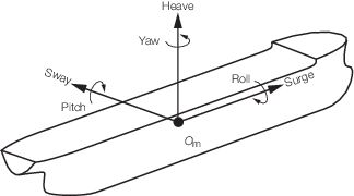
Figure 14.1.2 Ship coordinate system and sign
convention of motions
1.7.2 The
sign convention for ship motions and accelerations is shown in Figure 14.1.2 Ship coordinate system and sign
convention of motions. This is based on a
right-handed coordinate system. The roll, pitch and yaw motions are
defined positive clockwise as shown. For instance, positive sway is
defined as the translation toward port and positive pitch as the rotation
of the bow down and stern up.
|