
Section
6 Definitions
6.1 Principal particulars
6.1.1 Rule
length, L, is the distance, in metres, on the waterline
at draught T, from the forward side of the stem to the
after side of the rudder post or to the centre of the rudder stock
if there is no rudder post. L is to be not less than
96 per cent, and need not be greater than 97 per cent, of the extreme
length on the waterline. For ships without rudders, the Rule length
is to be taken as 97 per cent of the extreme length on the waterline.
In ships with unusual stem or stern arrangements the Rule length, L, will be specially considered.
6.1.2 Amidships
is to be taken as the middle of the Rule length, L, measuring
from the forward side of the stem.
6.1.3 Breadth, B, is the greatest moulded breadth, in metres.
6.1.4 Depth, D, is measured, in metres, at the middle of the length, L,
from top of keel to top of the deck beam at side on the uppermost
continuous deck, or as defined in appropriate Chapters. When a rounded
gunwale is arranged, the depth D is to be measured to
the continuation of the moulded deck line.
6.1.5 Draught, T, is the scantling draught, in metres, measured from top of
keel, and is not to be taken as less than the ‘summer draught’. Both of the draughts are
to be indicated on the midship plan, irrespective of whether or not they are of the same
value.
6.1.6 The
block coefficient, C
b, is the moulded block
coefficient at draught, T, based on Rule length, L,
and moulded breadth, B, as follows:
6.1.7 Length
between perpendiculars, L
pp, is the distance,
in metres, on the waterline at draught T, from the fore
side of the stem to the after side of the rudder post, or to the centre
of the rudder stock if there is no rudder post. In ships with unusual
stern arrangements the length, L
pp, will be
specially considered. The forward perpendicular, F.P., is the perpendicular
at the intersection of the waterline with the fore side of the stem.
The after perpendicular, A.P., is the perpendicular at the intersection
of the waterline with the after side of the rudder post. For ships
without a rudder post, the A.P. is the perpendicular at the intersection
of the waterline with the centreline of the rudder stock.
6.1.8 Load
line length, L
L, is to be taken as 96 per
cent of the total length on a waterline at 85 per cent of the least
moulded depth measured from the top of the keel, or as the length
from the fore side of the stem to the axis of the rudder stock on
that waterline, if that is greater. In ships designed with a rake
of keel, the waterline on which this length is measured is to be parallel
to the designed waterline. The length L
L is
to be measured in metres.
6.1.9 Load
line block coefficient, C
bL, is defined as:
where

|
= |
volume of the moulded
displacement, in m3, excluding appendages, taken at draught T
L
|
|
T
L
|
= |
moulded draught, in metres, measured to the waterline at 85
per cent of the least moulded depth. |
6.1.10 Maximum
service speed, V, means the maximum ahead service speed,
in knots, which the ship is designed to maintain, at the summer load
waterline at maximum propeller RPM and corresponding MCR.
6.1.11 Bow
reference height, Hb
, is defined as:
For ships less than 250 m in length:
For ships 250 m or greater in length:
6.2 Freeboard deck
6.2.1 The
freeboard deck is normally the uppermost complete deck exposed to
weather and sea, which has permanent means of closing all openings
in the weather part, and below which all openings in the sides of
the ship are fitted with permanent means of watertight closing.
6.2.2 For
the purposes of the Load Lines Conventions, as applicable, where the
assigned summer freeboard is increased such that the resulting draught
is not more than that corresponding to a minimum summer freeboard
for the same ship, but with an assumed freeboard deck located a distance
below the actual freeboard deck at least equal to the standard superstructure
height, the related items for the conditions of assignment to the
actual freeboard deck may be as required for a superstructure deck.
6.3 Bulkhead deck
6.3.1 For a passenger ship the bulkhead deck is generally to be taken as the deck to which
the main bulkheads and side shell are carried watertight.
6.3.2 For a cargo ship the bulkhead deck is generally to be taken as the freeboard
deck.
6.4 Weathertight
6.4.1 A closing
appliance is considered weathertight if it is designed to prevent
the passage of water into the ship in any sea conditions.
6.4.2 Generally,
all openings in the freeboard deck and in enclosed superstructures
are to be provided with weathertight closing appliances.
6.5 Watertight
6.5.1 A closing
appliance is considered watertight if it is designed to prevent the
passage of water in either direction under a head of water for which
the surrounding structure is designed.
6.5.2 Generally,
all openings below the freeboard deck in the outer shell/envelope
(and in main bulkheads) are to be fitted with permanent means of watertight
closing.
6.6 Position 1 and Position 2
6.6.1 For the purpose of Load Line conditions of assignment, there are two basic
positions of hatchways, doorways and ventilators defined as follows (see also
Figure 1.6.1 Position 1 and Position 2):
Position 1:
- Exposed decks located abaft the forward 0,25 of the load line
length, LL, and less than one standard superstructure height above
the freeboard deck.
- Exposed decks situated within the forward 0,25 of the load line
length, LL, and located less than two standard heights of
superstructure above the freeboard deck.
Position 2:
- Exposed decks situated abaft the forward 0,25 of the load line
length, LL, and located at least one standard height of
superstructure, but less than two standard heights of superstructure, above the
freeboard deck.
- Exposed decks situated within the forward 0,25 of the load line
length, LL, and located at least two standard heights of
superstructure, but less than three standard heights of superstructure, above the
freeboard deck.
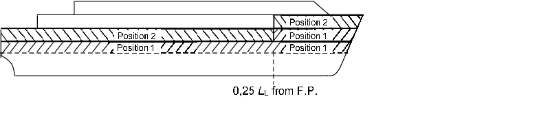
Figure 1.6.1 Position 1 and Position 2
6.7 Passenger ship
6.7.1 A passenger
ship is a ship which carries more than 12 passengers.
6.8 Reference system
6.8.1 For
hull reference purposes, the ship is divided into 21 equally spaced
stations where Station 0 is the after perpendicular, Station 20 is
the forward perpendicular, and Station 10 is mid-L
pp.
6.9 Co-ordinate system
6.9.1 Unless
otherwise stated, the co-ordinate system is as shown in Figure 1.6.2 Co-ordinate system, that is, a right-hand
co-ordinate system with the X axis positive forward, the Y axis positive
to port and the Z axis positive upwards. Angular motions are considered
positive in a clockwise direction about the X, Y or Z axes.
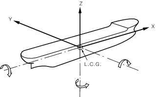
Figure 1.6.2 Co-ordinate system
6.10 Damage waterlines
6.10.1 The equilibrium waterline is the waterline in still water when, taking
account of flooding due to an assumed damage, the weight and buoyancy forces acting
on a ship are in balance. This relates to the final floating position, see
Figure 1.6.3 Damage heel angles, when no further
flooding takes place or after cross flooding is completed.
6.10.2 The intermediate waterline is the waterline in still water, which
represents the instantaneous floating position of a ship at some intermediate stage
between commencement and completion of flooding when, taking account of the assumed
instantaneous state of flooding, the weight and buoyancy forces acting on the ship
are in balance. The deepest intermediate waterline corresponds to the maximum
intermediate heel angle, see
Figure 1.6.3 Damage heel angles.
6.10.3 The intermittent waterline is the waterline in still water, which
represents the instantaneous floating position of a ship corresponding to the
intermittently immersed heel angle. The intermittently immersed heel angle,
see
Figure 1.6.3 Damage heel angles, is
the heel angle corresponding to the maximum range in the damage condition.
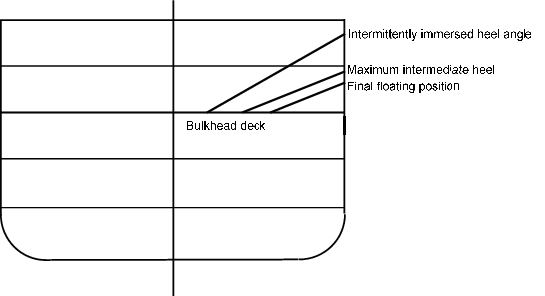
Figure 1.6.3 Damage heel angles
|