
Section
1 Highway live loads based on BS 5400 Part 2 1978 - HA and HB
1.1 General
1.1.1 This Section provides guidance on how to calculate highway loading.
Alternatively, highway loading is to be calculated in accordance with a recognised
National or International Standard and agreed with Lloyd’s Register.
1.1.2 Standard
highway loading consists of HA and HB loading.
1.1.3 HA
loading is a formula loading representing normal traffic in the U.K.:
- HB loading is an abnormal vehicle unit loading.
- Both loadings include an allowance for impact.
1.2 Type HA loading
1.2.1 Type HA loading consists of a uniformly distributed load, in
kN/m2, and a knife edge load, in kN/m, combined, or of a single wheel
load, see also
Pt 3, Ch 9, 1.2 Type HA loading 1.2.3.
1.2.2
Nominal uniformly distributed load (UDL). For loaded lengths up to and including
50 m, the UDL shall be derived from the equation:
where L is the loaded length, in metres.
For loaded lengths in excess of 50 m, the UDL shall be derived
from the equation:
but not less than 21,8 KN/m.
Alternatively, values for this load per linear metre of notional lane are
given in Table 9.1.1 Type HA Uniformly distributed
load.
1.2.3
Nominal
knife edge load (KEL). The KEL per notional lane shall be taken
as 120 kN.
1.2.4
Distribution. The UDL and KEL shall be taken to occupy one notional lane,
uniformly distributed over the full width of the lane, see
Figure 9.1.1 Distribution of UDL and
KEL.
The KEL is to be applied at only one point in the loaded length of the notional lane.
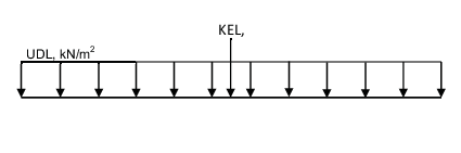
Figure 9.1.1 Distribution of UDL and
KEL
1.2.5
Dispersal. No allowance for the dispersal of the UDL and KEL shall be
made.
1.2.6
Single
nominal wheel load alternative to UDL and KEL. One 100 kN wheel,
placed on the carriageway and uniformly distributed over a circular
contact area assuming an effective pressure of 1,1 N/mm2 (i.e.
340 mm diameter), shall be considered.
Alternatively, a square contact area may be assumed, using the
same effective pressure (i.e. 300 mm side).
Table 9.1.1 Type HA Uniformly distributed
load
| Loaded length
|
Load, UDL
|
Load length
|
Load, URL
|
| m
|
kN/m
|
m
|
kN/m
|
| 2
|
211,2
|
44
|
26,6
|
| 4
|
132,7
|
47
|
25,5
|
| 6
|
101,2
|
50
|
24,4
|
| 8
|
83,4
|
55
|
24,1
|
| 10
|
71,8
|
60
|
23,9
|
| 12
|
63,6
|
65
|
23,7
|
| 14
|
57,3
|
70
|
23,5
|
| 16
|
52,4
|
75
|
23,4
|
| 18
|
48,5
|
80
|
23,2
|
| 20
|
45,1
|
85
|
23,1
|
| 23
|
41,1
|
90
|
23,0
|
| 26
|
37,9
|
100
|
22,7
|
| 29
|
35,2
|
110
|
22,5
|
| 32
|
33,0
|
120
|
22,3
|
| 35
|
31,0
|
130
|
22,1
|
| 38
|
29,4
|
150
|
21,8
|
| 41
|
27,9
|
|
|
1.2.7
Dispersal. Dispersal of the single nominal wheel load at a spread-to-depth
ratio of one horizontally to two vertically through asphalt and similar
surfacing may be assumed, where it is considered that this may take
place.
Dispersal through structural concrete slabs may be taken at
a spread-to-depth ratio of one horizontally to one vertically down
to the neutral axis.
1.3 Type HB Loading
1.3.1 For
all public highway bridges in Great Britain, the minimum number of
units of type HB loading that shall normally be considered is 30,
but this number may be increased up to 45 if so directed by the appropriate
authority.
For the purposes of these Rules these figures may also apply
to the bridges and ramps on a linkspan.
1.3.2
Nominal
HB loading.
Figure 9.1.2 Dimensions of HB vehicle shows
the plan and axle arrangement for one unit of nominal HB loading.
One unit shall be taken as equal to 10 kN per axle (i.e. 2,5 kN per
wheel).
The overall length of the HB vehicle shall be taken as 10, 15,
20, 25 or 30 m for inner axle spacings of 6, 11, 16, 21 or 26 m respectively,
and the effects of the most severe of these cases shall be adopted.
The overall width shall be taken as 3,5 m.
1.3.3
Contact
area. Nominal HB wheel loads shall be assumed to be uniformly
distributed over a circular contact area, assuming an effective pressure
of 1,1 N/mm2.
Alternatively, a square contact area may be assumed, using the
same effective pressure.
1.3.4
Dispersal. Dispersal of HB wheel loads at a spread-to-depth ratio of
one horizontally to two vertically through asphalt and similar surfacing
may be assumed, where it is considered that this may take place.
Dispersal through structural concrete slabs may be taken at
a spread-to-depth ratio of one horizontally to one vertically down
to the neutral axis.
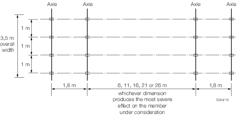
Figure 9.1.2 Dimensions of HB vehicle
1.4 Assessment of HA and HB loading
|