
Section
4 Design criteria
4.1 Allowable stress - Elastic failure
4.1.1 The
allowable stress, σa, is to be taken as the failure
stress of the component concerned multiplied by a stress factor, F,
which depends on the load case considered. The allowable stress is
given by the general expression:
where
|
σa
|
= |
allowable
direct stress, in N/mm2
|
|
τa
|
= |
allowable
shear stress, in N/mm2
|
|
F
|
= |
stress
factor |
|
σ, τ |
= |
failure
stress, in N/mm2.
|
4.1.2 The
stress factors, F, for steels in which 
where
|
σy
|
= |
yield
stress of material, in N/mm2
|
|
σu
|
= |
ultimate
tensile stress of the material, in N/mm2
|
are given in Table 5.4.1 Stress factor, F.
Table 5.4.1 Stress factor, F
| Load Case
|
1
|
2
|
3
|
| Stress factor, F
|
0,60
|
0,85
|
0,6
|
4.1.3 For
steel with  the allowable stress is to be derived from the following
expression: the allowable stress is to be derived from the following
expression:
4.1.4 The
failure stress for the elastic modes of failure are given in Table 5.4.2 Failure stress.
Table 5.4.2 Failure stress
| Mode of failure
|
Symbol
|
Failure stress
|
| Tension
|
σt
|
1,0σy
|
| Compression
|
σc
|
1,0σcr
|
| Shear
|
τ
|
0,58σy
|
| Bearing
|
σbr
|
1,0σy
|
4.1.5 For
components subjected to combined stresses the following allowable
stress criteria are to be used:
-
σxx < Fσt
-
σyy < Fσt
-
τo < Fτ
-
σ =
(σxx
2 + σyy
2 - σxx σyy + 3τo
2)1/2 ≤
1,1Fσt
where
|
σxx
|
= |
applied
stress in x direction, in N/mm2
|
|
σyy
|
= |
applied
stress in y direction, in N/mm2
|
|
τo
|
= |
applied
shear stress, in N/mm2.
|
4.2 Allowable stress - Compression and bending members
4.2.1 The
allowable axial stress for compression members is to be taken as the
critical compressive stress, σcr, multiplied by the
allowable stress factor, F, as defined in Table 5.4.1 Stress factor, F.
4.2.2 For
members subjected to simple compression the critical compression stress
is given by the Perry-Robertson formula below:
4.2.3 For
members subjected to combined bending and compression the following
stress criteria are to be used:
where
|
σbx
|
= |
applied
bending stress about the X-X axis, in N/mm2
|
|
σc
|
= |
applied
compression stress, in N/mm2
|
|
σby
|
= |
applied
bending stress about the Y-Y axis, in N/mm2.
|
4.3 Allowable stress - Plate buckling failure
4.3.1 The
allowable stress is to be taken as the critical buckling stress σcb, σbb, or τb as appropriate
of the component concerned multiplied by the stress factor, F,
as defined in Table 5.4.1 Stress factor, F.
4.3.2 For
components subject to compression the critical buckling stress is
given by:
-
for σcb < 0,5σy
-
for σcb ≥ 0,5σy
where
|
σcb
|
= |
critical
compression buckling stress, in N/mm2
|
|
σy
|
= |
yield stress, in N/mm2 |
|
E
|
= |
Young's
modulus, in N/mm2
|
|
t
|
= |
plate
thickness, in mm |
|
b
|
= |
plate
width, i.e. normal to direction of stress, in mm. |
4.3.3 For
components subject to shear, the critical buckling stress is given
by:
-
for τb <
0,29σy
-
for τb ≥
0,29σy
where
|
τb
|
= |
critical
shear buckling stress, in N/mm2
|
|
σy |
= |
yield stress, in N/mm2 |
|
E
|
= |
Young's
modulus, in N/mm2
|
|
t
|
= |
plate
thickness, in mm |
|
b
|
= |
smallest
plate dimension, in mm. |
|
Ks |
= |
shear buckling constant, defined as follows
where
|
α |
= |
 |
|
a |
= |
plate length corresponding to b |
The graphical representation of Ks is provided in Figure 5.4.2 Shear buckling constant Ks.
|
4.3.4 For
components subject to bending stress the critical buckling stress
is given by:
-
for σbb < 0,5σy
-
for σbb ≥ 0,5σy
where
|
σbb
|
= |
critical
buckling stress, in N/mm2
|
|
σy |
= |
yield stress, in N/mm2 |
|
E
|
= |
Young's
modulus, in N/mm2
|
|
t
|
= |
plate
thickness, in mm |
|
b
|
= |
plate
width, i.e. normal to direction of stress, in mm. |
|
Kb |
= |
bending buckling constant, defined as follows
for α ≥  :
for α <  :
where
|
α |
= |
 |
|
a |
= |
plate length, i.e. in the direction of stress |
The graphical representation of Kb is provided in Figure 5.4.3 Bending buckling constant Kb.
|
4.3.5 For
components subject to combined compression and shear, the following
allowable stress criteria are to be met:
-
σc < Fσcb
-
τ < Fτb
-

|
τ |
= |
applied shear
stress, in N/mm2.
|
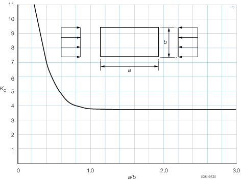
Figure 5.4.1 Compression buckling constant Kc
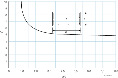
Figure 5.4.2 Shear buckling constant Ks
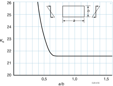
Figure 5.4.3 Bending buckling constant Kb
4.3.6 For
components subject to combined bending and shear, the following stress
criteria are to be met:
-
σb < Fσbb
-
τ < Fτb
-

Table 5.4.3 Values of Robertson Constant, a,
for various sections
| Type of section
|
Thickness of flange or plate, in mm
|
Axis of buckling
|
a
|
| Rolled section (universal
beams)
|
|
xx
|
2,0
|
| Roled H section (universal
columns
|
up to 40
|
xx
|
3,5
|
|
See Note 1
|
|
yy
|
5,5
|
|
|
over 40
|
xx
|
5,5
|
|
|
|
yy
|
8,0
|
| Welded plate or H sections
|
up to 40
|
xx
|
3,5
|
|
See Notes 1, 2 and 3
|
|
yy
|
5,5
|
|
|
over 40
|
xx
|
3,5
|
|
|
|
yy
|
8,0
|
| Rolled or H section with welded
flange cover plates
|
|
xx
|
3,5
|
|
See Notes 1 and 4
|
|
yy
|
|
|
|
|
xx
|
2,0
|
|
|
|
yy
|
|
| Welded box sections
|
up to 40
|
any
|
3,5
|
|
See Note 1, 3 and 4
|
over 40
|
any
|
5,5
|
| Rolled channel sections, rolled angle
sections and T-bars (rolled or cut from universal beam or column)
|
|
any
|
5,5
|
| Hot-rolled structural hollow
sections
|
|
any
|
2,0
|
| Rounds, square and flat bars
|
up to 40
|
any
|
3,5
|
|
See Note 1
|
Over 40
|
any
|
5,5
|
| Compound rolled sections (2 or more ,
H or channel sections, section plus channel, etc.)
|
|
any
|
5,5
|
| Two rolled angle, channel or
T-sections, back to back
|
|
any
|
5,5
|
| Two rolled sections laced or
battened
|
|
any
|
5,5
|
| Lattice strut
|
|
any
|
2,0
|
Note
1. For thickness between 40 mm and 50 mm
the value σcb, τb or σbb may be taken as the
average of the value for thicknesses less than 40 mm and the value for
thicknesses greater than 40 mm.
Note
2. For welded plate or H sections where
it can be guaranteed that the edges of the flanges will only be
flame-cut, a = 3,5 may be used for buckling about the y-y axis
for flanges up to 40 mm thick and , a = 5,5 for flanges over 40
mm thick.
Note
3. Yield strength for sections fabricated
from plate by welding reduced by 25 N/mm2.
Note
4. `Welded box sections' include those
fabricated from four plates, two angles or an or H section and two
plates but not box sections composed of two channels or plates with
welded logitudinals stiffeners.
|
Table 5.4.4 Value K, for different constraint
conditions
| Diagramatic
representation
|
Restraint conditions
|
K
|

|
Constrained against rotation and translation at
both ends
|
0,7
|
|
Constrained against rotation and translation at
one end and translation only at other end
|
0,85
|

|
Constrained against translation only at each
end
|
1,0
|

|
Constrained against rotation and translation at
one end and against rotation only at other end
|
1,5
|

|
Constrained against rotation and translation at
one end and free to rotate and translate at other end
|
2,0
|
4.3.7 For
components subject to combined bending and compression the following
allowable stress criteria are to be met:
-
σc < Fσcb
-
σb < Fσbb
-

4.3.8 For
components subject to combined compression, bending and shear, the
following allowable stress criteria are to be met:
-
σc < Fσcb
-
σb < Fσbb
-
τ < Fτb
-

4.4 Allowable stress - Joints and connections
4.4.1 For welded joints, the physical properties of the weld metal are considered
as equal to the parent metal. For full penetration butt welds, the allowable stress is
equal to the allowable stress of the parent material (see
Pt 3, Ch 5, 4.1 Allowable stress - Elastic failure).
4.4.2 For
fillet welds and welds subjected to shear, the allowable stresses
are reduced. Values of these reduced stresses are given in Table 5.4.5 Allowable stresses in welds,
N/mm2. Where, F,
is the stress factor, see
Table 5.4.1 Stress factor, F.
Table 5.4.5 Allowable stresses in welds,
N/mm2
| Type of weld
|
Allowable stress
|
| Direct
|
Shear
|
| Full penetration butt weld
|
1,0 Fσy
|
0,58 Fσy
|
| Fillet welds
|
0,7 Fσy
|
0,58 Fσy
|
4.4.3 The
design stress in fillet welds is to be calculated on the `throat'
dimension of the weld. See
Figure 5.4.4 Fillet weld dimensions.
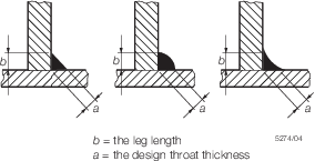
Figure 5.4.4 Fillet weld dimensions
4.4.4 The
strength of joints using pretensioned bolts to transmit shear and/or
tensile forces, e.g. high strength friction grip bolts, is to be determined
in accordance with an appropriate National or other acceptable code
or standard.
4.4.5 For
joints using precision bolts, defined as turned or cold finished bolts
fitted into drilled or reamed holes whose diameter is not greater
than the bolt diameter by more than 0,4 mm, the allowable stress due
to the externally applied load is given in Table 5.4.6 Allowable stresses for fitted
bolts.
4.4.6 Where
joints are subjected to fluctuating or reversal of load across the
joint the bolts are to be pretensioned by controlled means to between
70 and 80 per cent of their specified yield stress.
Table 5.4.6 Allowable stresses for fitted
bolts
| Type of
loading
|
Allowable
stress
|
| Load cases
|
Load case
|
| 1 and 3
|
2
|
| Tension
|
0,4 σy
|
0,54 σy
|
| Single shear
|
0,38 σy
|
0,51 σy
|
| Double shear
|
0,57 σy
|
0,77 σy
|
| Tension and shear
|
0,48 σy
|
0,64 σy
|
|
|
|
|
| Bearing
|
0,9 σy
|
1,2 σy
|
4.4.7 Black
bolts (ordinary grade bolts) are not to be used for primary joints
or joints subject to fatigue.
4.5 Deck plating thickness
4.5.1 The
deck plating thickness, t, for bridges and ramps is to
be adequate for the intended vehicle traffic and is to be calculated
with reference to the method described in Pt 3, Ch 4, 3.3 Deck plating.
4.6 Deflection criteria
4.6.1 In
Case 1 the deflection of the bridge or ramp between supports under
the applied load is to be limited to that given by the following expression:
where
|
L
|
= |
distance
between supports, in mm. |
4.6.2 For
cantilevered sections of bridges and ramps the deflection is to be
limited to  mm mm
where
|
L
|
= |
is
the length of the cantilevered section. |
4.7 Hoisting and slewing arrangements
4.7.1 Where
chains are used as part of the hoisting or slewing arrangement they
are to have a minimum safety factor of 4,0.
4.7.2 Where
wire ropes are used as part of the hoisting or slewing arrangement
the safety factor is to be determined as:
where
|
SF
|
= |
minimum
safety factor required |
|
W
|
= |
weight
of the ramp in tonnes (for ramps which are unloaded during manoeuvring) |
The actual design safety factor is to be not less than four
and need not be greater than five.
4.8 Locking arrangements
4.8.1 Where
bridges and ramps are raised or lowered in the unloaded condition
and then pinned or locked off to support both the dead weight and
vehicle loads, the pins (or locking device) are to be adequate for
the worst loading derived from Case 1 and are to satisfy the allowable
stress criteria of Pt 3, Ch 5, 4.1 Allowable stress - Elastic failure,Pt 3, Ch 5, 4.2 Allowable stress - Compression and bending members ,Pt 3, Ch 5, 4.3 Allowable stress - Plate buckling failure ,Pt 3, Ch 5, 4.4 Allowable stress - Joints and connections.
4.9 Safety restraints
4.9.1 Where
a bridge or ramp is retained in position by a single articulated mechanical
connection a suitable means is to be provided to prevent the complete
detachment of the bridge or ramp from the support in the event of
failure of the joint.
4.9.2 Chains
or wire ropes used for this purpose are to take due account of the
kinetic energy developed by the falling structure and are to have
a safety factor of at least two.
4.9.3 To
prevent movement and consequent failure, pins for all primary hinges
and articulations are to be locked in position by adequate keep plates,
castellated and wired nuts, end cover plates or other suitable means.
4.10 Deck gradients and transitions
4.10.1 The
gradients of bridges and ramps are in general not to exceed a slope
of 1 in 10 during normal operation with ships at lowest or highest
freeboard at Mean Low or High Water Spring Tides respectively. Additionally,
a maximum slope of 1 in 8 will be permitted for Lowest and Highest
Astronomical Tides.
4.10.2 Changes
in bridge or ramp gradients and transitions are to take account of
ground clearance of the vehicles using the linkspan throughout the
operational range.
|