
Section
8 Sternframes and appendages
8.1 General
8.1.1 Sternframes,
propeller bosses and shaft brackets may be constructed of forged or
cast steel, or may be fabricated from plate.
8.1.4 Sternframes,
shaft brackets, etc. are to be effectively integrated into the ship’s
structure and their design is to be such as to facilitate this.
8.2 Sternframes
8.2.1 The scantlings
of sternframes are to be determined from Table 5.8.1 Sternframes. The scantlings for sternframe configurations other than
described in this Section, and for cast steel sternframes, will be
specially considered, but the strength is to be at least equivalent
to a fabricated sternframe.
Table 5.8.1 Sternframes
| Item
|
Parameter
|
Requirement
|
|
|
|
Forged or roll
steel
|
Fabricated
steel
|
|
(1) Propeller posts
|
A
|
for L ≤ 60 m :  0,8T cm2 0,8T cm2
|
-
|
|
|
A
|
for L > 60 m : 32T
cm2
|
-
|
|
|
t
1
|
-
|
12 + 0,11L mm
|
|
|
r
|
-
|
18 + 0,17L mm
|
|
|
l
|
-
|
150  mm mm
|
|
|
W
|
-
|
100  mm mm
|
|
|
t
W
|
-
|
5 + 0,05L mm
|
|
(2) Sternpost in twin screw ships and non-propelled ships
|
A
|
for L ≤ 60 m :  0,7T cm2 0,7T cm2
|
-
|
|
|
A
|
for L > 60 m : 28T
cm2
|
-
|
|
|
t
1
|
-
|
8 + 0,07L mm
|
|
|
r
|
-
|
12 + 0,11L mm
|
|
|
l
|
-
|
150  mm mm
|
|
|
W
|
-
|
100  mm mm
|
|
|
t
W
|
-
|
5 + 0,05L mm
|
|
(3) Propeller shaft boss
|
tb
|

|
|
(4) Solepieces (open type sternframe) supporting the lower
rudder pintle
|
Z
T
|
c.f.Ar(V + 5,6)2 × (a/b –
0,15) × 0,95 a/b cm3
see Note 4
|
|
Z
V
|
0,5Z
T cm3
|
|
(5) Double arm shaft brackets
|
Z
T
|
(16 ×
10–6 × D
ts
3) + 8 cm3
|
|
N
|
≥ 0,05e mm
|
|
M:N
|
between 2,5 and 5
|
| Symbols
|
L, T are as defined in Pt 3, Ch 5, 1.4 Symbols and definitions 1.4.1
|
e
|
= |
length of the longest shaft bracket strut, in mm |
|
f
|
= |
coefficient dependent on type of rudder profile and
rudder angle, see
Table 12.2.5 Rudder coefficient f
in Chapter 12 for rudder
angles in excess of 45° no higher factors than those for rudder
angles of 45° need to be applied. |
|
k
o
|
= |
material factor, = (235/σo)
(24/σo) |
|
t
2
|
= |
10 mm for a propeller shaft boss integrated in the
sternframe or supported by a single arm bracket and t
2 = 0 for a propeller shaft boss supported by double arm
shaft brackets. |
|
t
b
|
= |
finished thickness of boss, in mm |
|
A
|
= |
cross-sectional area of forged or rolled steel stern
post, in cm2
|
|
A
r
|
= |
total rudder area, in m2
|
|
D
ts
|
= |
Required mild steel diameter of tail shaft in way of
the boss, in mm |
|
N
|
= |
the thickness of the shaft bracket strut, in mm |
|
V
|
= |
maximum service speed with the ship in loaded
condition, in km/h |
|
Z
T
|
= |
section modulus against transverse bending, in
cm3
|
|
Z
V
|
= |
section modulus against vertical bending, in
cm3
|
|
Note
1. In fabricated sternframes the
connection of the propeller post to the boss is to be by full
penetration welding.
Note
2. Solepieces supporting movable nozzles
will be specially considered.
Note
3. The support of a solepiece by a fixed
nozzle arrangement will be specially considered.
Note
4. The length 'a' of the solepiece
should be taken as not less than 0,4b in the formula for
Z
T.
|
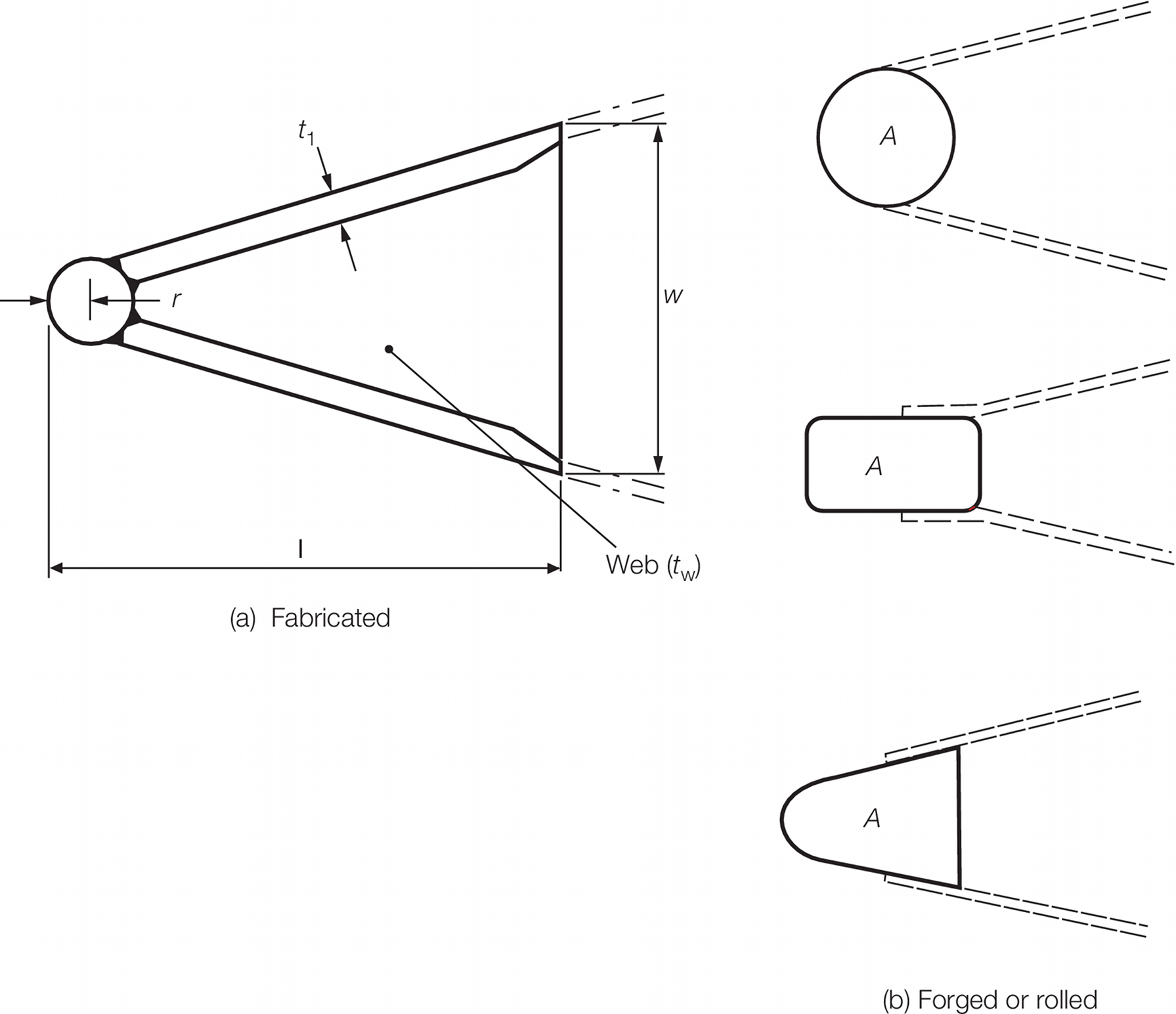
Figure 5.8.1 Propeller posts
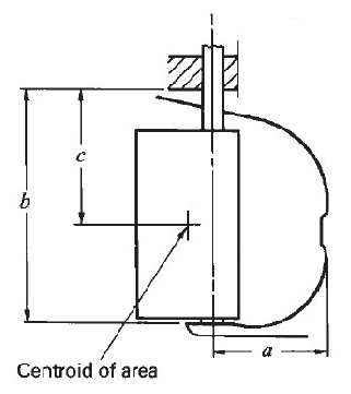
Figure 5.8.2 Open sternframe
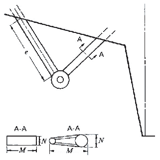
Figure 5.8.3 Shaft brackets
8.2.3 Fabricated
sternframes are to be strengthened by transverse webs, spaced not
more than 700 mm apart.
8.2.4 Solepieces
are to be carried well forward and efficiently scarfed into the keel.
Special care is to be taken to avoid any stress-raising details at
the point where the solepiece enters the shell plating.
8.2.5 Stern posts
and rudder stock lower bearings are to be connected to floors of which
the thickness is to be increased by 2 mm, above the thickness required
by Pt 3, Ch 5, 7.2 Bottom structure.
8.3 Propeller shaft bossing
8.3.1 The finished
thickness of the propeller boss in single and twin screw ships is
to comply with Table 5.8.1 Sternframes. The
length of the boss is to be adequate to accommodate the aftermost
shaft bearing, and to allow for a proper connection to the propeller
post or shaft brackets.
8.4 Shaft brackets
8.4.1 Where the
propeller shafting is exposed for some distance clear of the hull,
it is to be supported adjacent to the propeller by independent brackets
having two arms. The use of single arm brackets will receive special
consideration.
8.4.2 Shaft brackets
are to be designed to ensure a satisfactory connection to the internal
hull structure; hard spots are to be avoided. Bracket arms are generally
to be carried through the shell plating, which is to be locally increased
in thickness, see
Pt 3, Ch 5, 2.4 Shell plating 2.4.5.
The connection of the arms to the bearing boss and shell plating is
to be by full penetration welding.
8.4.3 The scantlings
of double arm shaft brackets are to comply with the requirements of Table 5.8.1 Sternframes. The scantlings of single
arm brackets will be specially considered.
|
| Copyright 2022 Clasifications Register Group Limited, International Maritime Organization, International Labour Organization or Maritime
and Coastguard Agency. All rights reserved. Clasifications Register Group Limited, its affiliates and subsidiaries and their respective
officers, employees or agents are, individually and collectively, referred to in this clause as 'Clasifications Register'. Clasifications
Register assumes no responsibility and shall not be liable to any person for any loss, damage or expense caused by reliance
on the information or advice in this document or howsoever provided, unless that person has signed a contract with the relevant
Clasifications Register entity for the provision of this information or advice and in that case any responsibility or liability is
exclusively on the terms and conditions set out in that contract.
|
 |
|