
Section
2 Hull envelope plating
2.1 General
2.1.1 This Section
covers the requirements for hull envelope plating, which includes
keel, stem, bottom shell plating, bilge plating, side shell plating,
sheerstrake and deck plating for the fore end and aft end of the ship.
Requirements are also given for tapering between the end thickness
and the midship 0,5L thickness.
2.2 Keel
2.2.1 The scantlings
of bar keels at the ends are to comply with Table 5.2.1 Shell plating forward and
aft.
Table 5.2.1 Shell plating forward and
aft
| Location
|
Scantlings
|
|
(1) Keel bars
|
t = 0,37L + 10 mm
Height = 0,7L + 75 mm
|
|
(2) Stem
|
The greater
of:
|
|
(a) Bar stem
|
A = 0,6L cm2
A = 10 cm2
|
|
(b) Plate stem
|
t = 0,08L + 5 mm
|
|
(3) Bottom shell, bilge and side shell plating forward and
aft of the respective shoulders
|
|
|
(a) Forward of 0,075L from the F.P. and aft of
0,075L from the A.P. (end thickness)
|
The greater of:
t = (5,6 + 0,054L)  mm mm
t = 10s mm
|
|
(b) Between 0,075L and 0,25L from the F.P. and
between 0,075L and 0,25L from the A.P.
|
The taper
thickness as determined from the midship thickness and the end thickness
using a taper line as per Pt 3, Ch 3, 2.5 Principles for taper
|
|
(4) Bilge chine bars
|
The greater
of:
|
|
(a) Round bars
|
Diameter = 3t
a mm
Diameter = 30 mm
|
|
(b) Solid square bars
|
The greater of:
Width = 3t
a mm
Width = 30 mm
|
|
(c) Angle bars in square bilges
|
Flange thickness = 2t
a mm
|
| Symbols
|
L, s and t as defined in Pt 3, Ch 5, 1.4 Symbols and definitions 1.4.1
|
A
|
= |
cross sectional area of bar stem, in cm2
|
|
t
a
|
= |
thickness of the bottom plating amidships, in mm |
|
2.2.2 The thickness
of the keel plate forward of the collision bulkhead is to be the stem
plate thickness; aft of the collision bulkhead the keel plate thickness
is to be as required for the midship region. The width of the keel
plate is to be 0,1B at the collision bulkhead and may
be tapered towards the stem.
2.2.3 The thickness
of the keel plate aft is to be as required for the midship region.
The width of the keel plate is to be 0,1B at the aft
peak bulkhead and may be tapered towards the aft end.
2.3 Stem
2.3.2 The thickness
of plate stems is to be determined from Table 5.2.1 Shell plating forward and
aft. Plate stems are to be supported by horizontal diaphragms,
spaced about 1 m apart and extended to the nearest frame. Where the
stem plate radius is large, a centreline stiffener or web will be
required. The thickness of plate stems from 1 m above the deepest
load waterline may be equal to the local shell thickness.
2.4 Shell plating
2.4.2 The amidships
thickness of the bilge plating is to be extended forward and aft to
include the shoulders of the bilge. The shoulder is regarded to extend
to where the upper edge of the bilge strake forward and aft reaches
the point 0,5B — 0,5 m.
2.4.3 Where a
bilge chine bar is used in a bilge arrangement, the scantlings of
chine bars are to comply with Table 5.2.1 Shell plating forward and
aft, and adjacent bottom and side shell plating need not
be increased in thickness.
2.4.5 The thickness
of shell plating is to be increased locally in way of the sternframe,
propeller brackets and rudder trunks. The increased plate thickness
is to be not less than 50 per cent greater than the basic shell end
thickness. The shell plating in way of hawse pipes is to be increased
in thickness by 3 mm.
2.4.6 Where a
swim end is arranged, the bottom shell plating thickness amidships
is to be maintained up to the end of the rake plating.
2.5 Shell openings
2.5.1 In general,
compensation will not be required for holes in the shell plating forward
and aft, provided the holes are of well rounded shape, but reinforcements
in way of large openings may be required.
2.6 Deck plating
2.6.1 The thickness
of deck plating is to comply with the requirements of Table 5.2.2 Deck plating forward and
aft.
Table 5.2.2 Deck plating forward and
aft
| Location
|
Thickness, in
mm
|
|
(1) Forward of 0,075L from the F.P. and aft of
0,075L from the A.P. on the strength deck
|
The greatest of:
|
t
|
= |
(5,6 + 0,039L) 
|
|
|
(2) Between 0,075L and 0,25L from the F.P. and
between 0,075L and 0,25L from the A.P. on the strength deck
|
The greatest of:
|
t
|
= |
(5,6 + 0,039L) 
|
see Note
|
|
(3) Platform decks
|
The greater of:
|
|
(4) In way of crown or bottom of a tank
|
The greater of:
t as in (1), (2) or (3) as applicable, but not less than
|
t
|
= |
5 mm for oil tanks, or |
|
t
|
= |
5,5 mm for water ballast tanks |
|
|
(5) Plating forming the upper flange of under deck
girders
|
The greater of:
|
t
|
= |
 with a minimum breadth with a minimum breadth |
t as in (1), (2), (3) or (4) as applicable
|
| Symbols
|
L, s and t are as defined in Pt 3, Ch 5, 1.4 Symbols and definitions 1.4.1
|
A
f
|
= |
girder face area, in cm2
|
|
b
|
= |
breadth of increased plating, in metres |
|
|
|
2.6.2 For ships
with wide hatch openings, in addition to the requirements for minimum
deck thickness forward given in Pt 3, Ch 5, 2.6 Deck plating 2.6.1,
the total cross-sectional area of strength deck plating and longitudinal
stiffening outside the line of main hatch openings is to be not less
than that obtained from a taper line constructed as shown in Figure 5.2.1 Strength deck area taper.
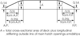
Figure 5.2.1 Strength deck area taper
2.6.3 The deck
plating thickness and supporting structure are to be suitably reinforced
in way of the anchor windlass, steering gear and other deck machinery,
and in way of bollards, cranes, masts or derrick posts.
2.7 Deck openings
2.7.1 Compensation
and edge reinforcement for openings in the upper deck forward of 0,25L from the F.P. and aft of 0,25L from the A.P.
may be required.
|