
Section
1 General
1.1 Introduction
1.1.3 A typical arrangement of an OPTS is shown in Figure 1.1.1 Typical arrangement and
components of an OPTS and
the typical parts of an OPTS consist of:
- pedestal or foundation (not part of the mothership
structure);
- motion compensation system (optional);
- base frame;
- machinery housing (may not necessarily be mounted on the
base frame);
- Operator station (ideally placed close to the gangway);
- gangway, main part;
- gangway, telescopic part (usually installed but may also
be optional); and
- landing or connecting arrangement.
Other possible arrangements and layouts of an OPTS may not use all of the
shown parts and/or may use other components and arrangements.
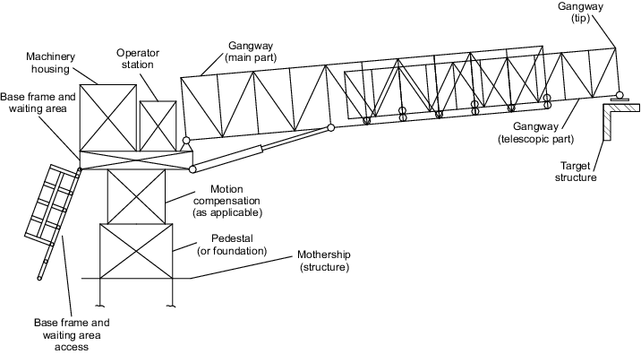
Figure 1.1.1 Typical arrangement and
components of an OPTS
1.1.4 The operational and functional sequence of a typical motion compensated
OPTS as shown in Figure 1.1.1 Typical arrangement and
components of an OPTS may
be described as outlined in Table 1.1.1 Operational and functional
sequence of a typical motion compensated OPTS.
Table 1.1.1 Operational and functional
sequence of a typical motion compensated OPTS
| Operational step
|
Service condition
|
Persons on gangway
|
Functional/operational
description
|
| 1
|
Out-of-service
|
No
|
The OPTS is securely
stowed on deck of the mothership.
|
| 2
|
Out-of-service
|
No
|
The Operator prepares the
OPTS for service (e.g. release of stowage arrangements) and
takes position at the Operator station.
|
| 3
|
In-service
|
Possible
|
Personnel are boarding the
waiting area on the OPTS (directly or via the gangway).
|
| 4
|
In-service
|
No
|
The OPTS is powered
up.
|
| 5
|
In-service
|
No
|
The base frame and the
gangway are lifted up from their resting positions and the OPTS
is slewing to the off-board position.
|
| 6
|
In-service
|
No
|
The motion compensation
system (and the base frame) is taken to its neutral position
(usually in between maximum positions).
|
| 7
|
In-service
|
No
|
The motion compensation
system is activated.
|
| 8
|
In-service
|
No
|
The gangway will be luffed
up or down to adjust for a potential height difference between
the waiting area on the base frame and the target
structure.
|
| 9
|
In-service
|
No
|
The telescopic part of the
gangway will be extended towards the target structure on the
target unit.
|
| 10
|
In-service
|
No
|
The gangway
landing/connection arrangement:
- may land on;
- may be pushed against;
- may be structurally secured to;
the target structure to enable a safe
transfer of personnel.
|
| 11
|
In-service
|
No
|
The system may be switched
into a lower level of motion compensation where slewing and/or
telescoping and/or luffing are partly and passively compensating
mothership motions without external power supply.
|
| 12
|
In-service
|
Yes
|
The system is in active or
passive compensation mode and personnel may access the gangway
and transfer to the target unit, if allowed by the
Operator.
|
| 13
|
In-service
|
No
|
The system regains full
motion compensation and slewing and/or telescoping and/or
luffing are back to powered compensation.
|
| 14
|
In-service
|
No
|
The gangway
landing/connection arrangement is disconnected from target
structure by telescoping in.
|
| 15
|
In-service
|
No
|
The motion compensation
system (and the base frame) is taken to its neutral position
(see operational step 6).
|
| 16
|
In-service
|
No
|
The base frame and the
gangway are lowered to their resting positions.
|
| 17
|
In-service
|
Possible
|
The transferring personnel
is leaving the OPTS via the waiting area or via the
gangway.
|
| 18
|
Out-of-service
|
No
|
The OPTS is powered
down.
|
| 19
|
Out-of-service
|
No
|
The Operator secures the
OPTS on the mothership deck in its stowage position.
|
1.1.5 In certain circumstances the requirements of this Code may not
adequately cover the actual project, e.g. due to novel design or other reasons. In
such circumstances, the applicability of this Code may require further consideration
in which case it is recommended to contact LR at an early stage in order to discuss
and agree the specific technical requirements and the certification or
classification approach. In all circumstances, however, a specific risk assessment
as defined in Ch 1, 10 Risk assessment will be required.
1.1.6 In general, the lifting and supporting of persons with lifting
appliances in an offshore or open sea environment is regarded as an activity posing
higher risks for personnel compared to normal cargo handling operations. The
requirements in this document are intended to mitigate such elevated risks.
1.2 Scope
1.2.1 This Code covers the design, fabrication, survey and documentation
requirements for an OPTS. However, it should be noted that the requirements of Ch 1 General, Ch 4 Cranes and Submersible Lifting Appliances, Ch 8 Fittings, Loose Gear and Ropes, Ch 9 Machinery, Ch 10 Electrotechnical Systems, Ch 11 Materials and Fabrication, Ch 12 Testing, Marking and Surveys and Ch 13 Documentation of the Code for Lifting Appliances in a Marine Environment, July 2022 also apply (as applicable) except in such instances where
the specific requirements are otherwise defined in this Code.
1.2.2 OPTS for the purposes of these requirements cover the following systems:
- Systems installed on motherships providing safe passage
to fixed installations in open sea conditions by means of passive, active or
hybrid compensation systems (e.g. mothership to fixed wind energy offshore
structures). These three systems are defined in Ch 1, 2 Offshore Personnel Transfer System types.
- Systems installed on motherships providing safe passage
to other ships or offshore units or floating installations in open sea
conditions by means of passive, active or hybrid compensation systems (e.g.
mothership to ship transfer).
- Systems which are ‘bridging’ two floating structures in
open sea conditions (e.g. bridging of a ‘Flotel’ and an FPSO) usually by
means of passive compensation systems.
- Systems which fulfil a dual function of providing safe
transfer between installations and/or ships and/or offshore units in open
sea conditions and also providing cargo handling capabilities.
- Systems without a gangway but equipped with a personnel
containment such as a basket or other type of carrier which contains or
supports personnel for the purposes of transfer from the mothership to the
target unit (e.g. from mothership to fixed wind energy offshore structures).
- Systems not described in the above will be specially
considered on the basis of this Code and the Code for Lifting Appliances in a Marine Environment, July 2022. See
Ch 1, 1.1 Introduction.
1.2.3 The scope of this Code with respect to certification and classification
of the OPTS does not extend to:
- any aspects related to the operation of the OPTS;
- systems operating at an ambient air temperature below
-50°C;
- systems operating at an ambient air temperature above
+45°C;
- systems designed for minimum design temperatures below
-40°C (see
Ch 4, 2.25 Materials of the Code for Lifting Appliances in a Marine Environment, July 2022);
- gangway construction materials other than steel;
- systems with the gangway at an inclination of more than
20 degrees (with personnel on the gangway);
- ship to shore gangways and linkspans;
- structure of the mothership in way of the
pedestal/foundation;
- lifting, handling and erection of the OPTS or their
components;
- transport of an OPTS and/or its components;
- accidental collision loads, e.g. collision of the OPTS
with a structure or an object, etc.;
- explosion/blast loads;
- assembling or disassembling of the OPTS and/or its
components;
- scrapping or disabling of the OPTS and/or its
components;
- handling of loads (e.g. cargo) using the (optional)
dedicated crane functionality simultaneous with the transfer operation of
personnel;
- an OPTS being installed on naval vessels where the
mothership and/or target unit are moving during transfer; and
- any misuse.
1.2.4 Where an OPTS also serves as a conventional offshore crane in addition to
its personnel transfer functionality then the OPTS shall be designed in accordance
with the applicable requirements of the Code for Lifting Appliances in a Marine Environment, July 2022 in addition to the requirements given in this Code. In case
of any conflict the more onerous requirement shall prevail. It is recommended that
LR is contacted at an early stage in order to agree on a resolution of such issues.
1.2.5 In order for this Code to be applicable it is required that the ships
and/or floating units and/or offshore units are moored or a Dynamic Positioning
System or a Positional Mooring System is installed on the mothership supporting the
OPTS or which is served by the OPTS. The capability and performance of the position
keeping system and its reference systems are to be taken into account and are to
ensure safe operation of the OPTS in all environmental conditions for which the
personnel transfer system is designed. The requirement for the installation of
position keeping systems will be specially considered in case of small vessels or
other circumstances (e.g. low operational significant waves heights) where such
systems may be unreasonable or may not be applicable.
1.2.6 The OPTS is to be designed considering the individual characteristics of
the mothership. Such individual characteristics can be related to mothership
motions, mothership inclination, station keeping performance, etc. If the mothership
is unknown at the time of design, a design load envelope shall be defined which
includes design accelerations, inclinations and other loads and limiting parameters.
1.2.7 In case of a non-permanently installed OPTS, the design is to make
reference to a design envelope taking into account the maximum governing loads
required to be applied for the design of the OPTS. Any operational parameters and
safety requirements or any limitations as a result of the design of OPTS are to be
taken into consideration. It is to be ensured the aforementioned loads,
requirements, parameters and limitations of the actual OPTS are not exceeded when
installing and operating the OPTS on the actual temporary mothership.
1.3 Stakeholders
1.3.1 This Code is considered relevant to the following stakeholders:
- National and/or Coastal State Authorities.
- Owners and/or Operators of units and ships on which OPTS
are installed.
- Designers/manufacturers responsible for the design,
production and installation of OPTS.
- Lloyd’s Register plan appraisal Specialists.
- Lloyd’s Register site Surveyors.
1.4 Prerequisites
1.4.1 OPTS built in accordance with the requirements of this Code will be classed or
certified and will continue to be classed and certified as long as they are found,
upon examination at the prescribed surveys, to be maintained in accordance with the
requirements of the Code.
1.4.2 These requirements are framed on the understanding that:
- The OPTS and/or associated components and/or equipment
will at all times be properly operated and loaded in accordance with the
designer’s or manufacturer’s instructions and the loading conditions
approved by LR.
- Where the OPTS and/or associated components and/or
equipment is to be certified but not classed, the design criteria specified
conclude that Periodical Survey procedures, at least equivalent to LR’s,
will be adhered to by the Owner or the OPTS Operator.
- The OPTS and/or associated components and/or equipment
will at all times be properly operated by authorised personnel who are
sufficiently competent, trained and qualified.
- The OPTS and/or associated components and/or equipment
will be maintained by authorised personnel who are sufficiently competent,
trained and qualified.
- The OPTS installed on the mothership will not be
operated in environmental conditions more severe than those agreed for the
design basis and approval and shall not be subjected to marine operational
conditions that exceed the parameters used in design and established
according to this Code.
- Before performing a personnel transfer operation, the
Operator will ensure that the actual mothership (and target unit) motion
parameters at current sea state, the current wind speed, the actual
elevation gap between mothership and target unit and the required range of
the telescoping system and other relevant parameters, do not exceed the
limiting values as defined by the individual design and specified in the
instructions for use. Marine and offshore contractors and the Operator
responsible for personnel transfer operations will be informed of these
limitations and the necessary restrictions during the personnel transfer
operations will be put in place.
- The OPTS and/or associated components and/or equipment
and surroundings will be thoroughly inspected by the Operator prior to use
as required by the instructions for use.
- The manufacturer is to have a documented quality
assurance system in place (including a continuous improvement system) in
compliance with a recognised National or International Standard, e.g. ISO
9001 Quality management systems – Requirements. For further details
see
Ch 1, 11 Quality assurance system.
- Compliance with these requirements does not absolve the
designers and/or manufacturers of their contractual responsibilities to the
Owner/Operator for compliance with the specification and the overall design
and in-service performance of the OPTS and/or associated components and/or
equipment.
- It is the responsibility of the Operator or Owner to
ensure that the OPTS is safely operated in compliance with the instructions
for use issued by the designer/manufacturer.
1.5 Authority requirements
1.5.1 The responsible National Authority (i.e. Flag State) and/or Coastal State and/or
other regulatory authorities responsible for the offshore sector in which the OPTS
is intended to be operated may have additional requirements which need to be adhered
to as applicable in addition to these requirements.
1.5.2 In case of conflict with this Code, the requirements of the National
Authority and/or Coastal State and/or other regulatory authorities take
precedence.
1.6 Classification procedure
1.6.2 The classification of the OPTS covers the design, construction, examination, testing
and subsequent Periodical Surveys to the extent indicated within this Code and is
achieved by way of the engagement of LR Surveyors at the appropriate stages of
design, construction, installation, commissioning, and periodical examinations
during service. The following activities are undertaken by LR:
- Appraisal of plans covering structural, mechanical,
hydraulic, electrical and control engineering aspects of the OPTS.
- Verification that the material for structural components
and machinery items adopted for a classed OPTS complies with Ch 1, 12 Materials and fabrication of these requirements. The required documentation for the
materials used is to comply with Ch 1, 12 Materials and fabrication and Ch 1, 12.8 Documentation 12.8.2.
- Survey during fabrication of the critical and primary
structure and winches, hydraulic cylinders and other machinery, parts and
components at the place of manufacture, including verifying that materials
are in accordance with the approved plans and suitably qualified welders
using approved weld procedures are employed in the fabrication. Further
details are provided in Ch 1, 12 Materials and fabrication.
- Survey at the manufacturer to include the hydraulic,
electrical and control engineering systems.
- Verification of certificates for the appropriate forms
of wire ropes and chains which are to be manufactured at works approved by
LR.
- Survey of the gangway and remaining critical and primary
structure, winches, electrical, control and hydraulic systems during
installation and on-site assembly.
- Survey and testing of the motion compensation,
connection and disconnection systems and arrangements (as applicable).
- Survey during load and operational testing of the OPTS,
as specified in Ch 1, 13 Testing, marking and surveys.
- Periodical Surveys and tests, as specified in Ch 1, 13.9 Classification surveys.
1.6.4 The classification of an existing OPTS or an OPTS which is not permanently installed
on a specific unit or mothership will be specially considered.
1.7 Certification procedure
1.7.1 Where certification, which is distinct from classification, of the OPTS
is requested, the procedures to be adopted are the same as those for classification
outlined in Ch 1, 1.6 Classification procedure, with the
following exceptions:
- The required documentation for the materials used may
comply with Ch 1, 12.8 Documentation 12.8.3.
- A class notation will not be assigned to certified
OPTS.
- Periodical Surveys after commissioning of the OPTS need
not be carried out by LR. However, the Owner’s/Operator’s/designer’s
attention is drawn to Ch 1, 13.5 Periodical thorough examinations
with respect to the need for ongoing Surveys.
1.7.2 The certification of an existing OPTS will be carried out following the
procedure as given in Ch 1, 13.4 Initial Survey of existing installations.
The certification of an OPTS which is not permanently installed on a specific unit
or mothership will be specially considered.
1.8 Class notations
1.8.1 If the OPTS forms an essential feature of the mothership, the mandatory
class notation LA shall be applied.
1.8.2 The special feature class notation which may optionally be applied to
OPTS is defined as W2W.
1.9 Referenced Rules, Codes and Standards
1.9.1 The authority requirements and the requirements of Codes, Rules and Standards listed
in the following are to be applied in the following order of priority:
- The requirements of the National and/or Coastal State
Authorities and/or other regulatory authorities (responsible for the mothership
and/or the offshore area of operation respectively).
- The requirements of this Code for Offshore Personnel
Transfer Systems.
- The requirements of Lloyd’s Register’s Code for Lifting Appliances in a Marine Environment, July 2022.
- Other Lloyd’s Register Rules and Standards (as applicable);
and
- The list of ISO, EN and other standards (see
Ch 1, 1.9 Referenced Rules, Codes and Standards 1.9.5 and Ch 1, 1.9 Referenced Rules, Codes and Standards 1.9.6) provides a list of
preferred standards in case requirements are considered
necessary to be taken from such standards in the absence of
requirements in (a), (b), (c) or (d) above. However, the
application of such additional standards shall be agreed
between the Owner and/or Operator, designer/manufacturer of
the OPTS and LR as applicable and required for the
individual project on a case-by-case basis.
The order of standards may also depend on the requirements of the
National and/or Coastal State Authorities responsible for the ship
and/or the offshore area of operation respectively. The selection of
standards as defined in Ch 1, 1.9 Referenced Rules, Codes and Standards 1.9.1.(e) shall be agreed with
LR prior to commencing of the project.
1.9.2 The edition or version of the Rules, Codes or standards shall be the one being in
force on the contract date between the Owner/Operator and the yard building the
mothership. Where designs and/or projects are not related to a specific mothership,
the edition or version of the applicable Rules, Codes or Standards shall be the one
being in force on the contract date between the designer/manufacturer and LR for
certification of the OPTS.
1.9.3 If a recognised National or International Standard listed in the following has been
withdrawn it shall no longer be used unless it has been replaced by another valid
and recognised standard.
1.9.4 Lloyd’s Register Rules, Codes and Procedures;
- Code for Lifting Appliances in a Marine Environment, July 2022,
- Rules for the Manufacture, Testing and Certification of Materials, July 2022,
- Rules and Regulations for the Classification of Ships, July 2022,
- Rules and Regulations for the Classification of Offshore Units, July 2022,
- Rules for the Winterisation of Ships, July 2022,
- ShipRight Procedure Cyber Security for Ships and
Ships Systems,
- ShipRight Procedure Risk Based Certification
(RBC).
1.9.5 European standards:
- EN 614 Safety of machinery – Ergonomic design
principles,
- EN 842 Safety of machinery – Visual danger
signals – General requirements, design and testing,
- EN 1127-1 Explosive atmospheres – Explosion
prevention and protection – Part 1: Basic
concepts and methodology,
- EN 10204 Metallic products – Types of inspection
documents,
- EN 12077-2 Cranes safety – Requirements for health
and safety – Part 2: Limiting and indicating devices,
- EN 12385-1 Steel wire ropes – Safety – Part 1:
General requirements,
- EN 12385-2 Steel wire ropes – Safety – Part 2:
Definitions, designation and classification,
- EN 12385-3 Steel wire ropes – Safety – Part 3:
Information for use and maintenance,
- EN 12385-4 Steel wire ropes – Safety – Part 4:
Stranded ropes for general lifting applications,
- EN 12644-1 Cranes – Information for use and testing –
Part 1: Instructions,
- EN 12644-2 Cranes – Information for use and testing –
Part 2: Marking,
- EN 13001 Cranes – General design,
- EN 13135 Cranes – Safety – Design – Requirements for
equipment,
- EN 13411-3 Terminations for steel wire ropes – Safety
– Part 3: Ferrules and ferrule-securing,
- EN 13411-4 Terminations for steel wire ropes – Safety
– Part 4: Metal and resin socketing,
- EN 13411-6 Terminations for steel wire ropes – Safety
– Part 6: Asymmetric wedge socket,
- EN 13411-7 Terminations for steel wire ropes – Safety
– Part 7: Symmetric wedge socket,
- EN 13557 Cranes – Controls and control
stations,
- EN 13586 Cranes – Access,
- EN 13852-1 Cranes – General-purpose offshore
cranes,
- EN 14502-1 Cranes – Equipment for the lifting of
persons – Part 1: Suspended baskets,
- EN 14502-2 Cranes – Equipment for the lifting
of persons – Part 2: Elevating control
stations,
- EN 31010 Risk management – Risk assessment
techniques.
1.9.6 International Standards:
- ISO Guide 73 Risk management – Vocabulary,
- ISO 281 Rolling bearings – Dynamic load ratings and
rating life,
- ISO 898 Mechanical properties of fasteners made of
carbon steel and alloy steel,
- ISO 15138 Petroleum and natural gas
industries – Offshore production installations –
Heating, ventilation and air
conditioning,
- ISO 2232 Round Drawn Wire for General Purpose
Nonalloy Steel Wire Ropes – Specifications,
- ISO 2408 Steel wire ropes – Requirements,
- ISO 2923 Acoustics – Measurement of Noise on
Board Vessels,
- ISO 3108 Steel wire ropes – Test method
– Determination of measured breaking
force,
- ISO 3744 Acoustics – Determination of sound power
levels and sound energy levels of noise sources using sound pressure —
Engineering methods for an essentially free field over a reflecting
plane,
- ISO 4309 Cranes – Wire ropes – Care and maintenance,
inspection and discard,
- ISO 4413 Hydraulic fluid power – General rules and
safety requirements for systems and their components,
- ISO 4414 Pneumatic fluid power – General rules
and safety requirements for systems and their
components,
- ISO 4871 Acoustics – Declaration and verification of
noise emission values of machinery and equipment,
- ISO 5488 Ships and marine technology – Accommodation
ladders,
- ISO 5817 Welding – Fusion-welded joints in steel,
nickel, titanium and their alloys (beam welding excluded) – Quality
levels for imperfections,
- ISO 6336 Calculation of load capacity of spur and
helical gears,
- ISO 7010 Graphical symbols – Safety colours
and safety signs – Registered safety
signs,
- ISO 7061 Ships and marine technology – Aluminium
shore gangways for seagoing vessels,
- ISO 7731 Ergonomics – Danger signals for public and
work areas – Auditory danger signals,
- ISO 8566-1 Cranes – Cabins and control stations –
Part 1: General,
- ISO 9001 Quality management systems –
Requirements,
- ISO 9712 Non-destructive testing –
Qualification and certification of NDT
personnel,
- ISO 9927-1 Cranes – Inspections – Part 1:
General,
- ISO 10474 Steel and steel products – Inspection
documents,
- ISO 11201 Acoustics – Noise emitted by machinery and
equipment – Determination of emission sound pressure levels at a work
station and at other specified positions in an essentially free field
over a reflecting plane with negligible environmental
corrections,
- ISO 11688 Acoustics – Recommended practice for the
design of low-noise machinery and equipment,
- ISO 12100 Safety of machinery – General principles
for design – Risk assessment and risk reduction,
- ISO 12478-1 Cranes – Maintenance manual – Part 1:
General,
- ISO 12480-1 Cranes – Safe use – Part 1:
General,
- ISO 12482-1 Cranes – Condition monitoring – Part 1:
General,
- ISO 12944 Paints and varnishes – Corrosion protection
of steel structures by protective paint systems,
- ISO 13702 Petroleum and natural gas industries
– Control and mitigation of fires and
explosions on offshore production installations
– Requirements and guidelines,
- ISO 13849 Safety of machinery – Safety-related
parts of the control systems,
- ISO 13850 Safety of machinery – Emergency stop
function – Principles for design,
- ISO 14120 Safety of machinery – Guards –
General requirements for the design and
construction of fixed and movable guards,
- ISO 14122 Safety of machinery – Permanent
means of access to machinery,
- ISO 17894 Ships and marine technology – Computer
applications – General principles for the development and use of
programmable electronic systems in marine applications,
- ISO 19353 Safety of machinery – Fire prevention and
fire protection,
- ISO 20332 Cranes – Proof of competence of steel
structures,
- ISO 31000 Risk management – Guidelines,
- IEC 60079 Explosive atmospheres,
- IEC 60092-502 Electrical installations in ships
– Part 502: Tankers - Special
features,
- IEC 60529 Degrees of protection provided by
enclosures (IP Code),
- IEC 61000 Electromagnetic compatibility
(EMC),
- IEC 60204-32 Safety of machinery – Electrical
equipment of machines – Part 32: Requirements for hoisting
machines,
- IEC 60812 Analysis techniques for system reliability
– Procedure for failure mode and effects analysis (FMEA),
- IEC 61508 Functional safety of electrical/
electronic/ programmable electronic safety-related systems,
- IEC 61882 Hazard and Operability Studies (HAZOP
Studies) – Application Guide,
- IEC 61892-7 Mobile and fixed offshore units –
Electrical installations – Part 7:
Hazardous areas,
- IEC 62443 Security for industrial
automation and control systems,
- IEC 62745 Safety of machinery – Requirements
for cableless control systems of
machinery,
- ISO 80079-36 Explosive atmospheres – Part 36:
Non-electrical equipment for explosive atmospheres – Basic method and
requirements,
- ISO/IEC 27001 Information technology –
Security techniques – Information security
management systems – Requirements,
- ISO/IEC 90003 Software engineering – Guidelines for
the application of ISO 9001:2008 to computer software,
- IMO MSC.1/Circ. 1331 Guidelines for construction,
installation, maintenance and inspection/survey of means of embarkation
and disembarkation,
- IMO Code on Alerts and Indicators, 2009,
- IMO International Code for the Application of Fire
Test Procedures (2010 FTP Code),
- IMO Code for the Construction and Equipment of Mobile
Offshore Drilling Units (2009 MODU Code),
- IMO International Convention for the Safety of Life
at Sea (SOLAS), 1974,
- IMO SOLAS regulation II-1/3-9, Means of embarkation
on and disembarkation from ships,
- F.E.M. 1.001 Rules for the design of hoisting
appliances,
- EI Model Code of Safe Practice Part 15: Area
Classification for Installations Handling Flammable Fluids,
- ANSI/ISEA 121 American National Standard for Dropped
Object Prevention Solutions,
- API RP 505 Recommended Practice for Classification of
Locations for Electrical Installations at Petroleum Facilities
Classified as Class I, Zone 0, Zone 1, and Zone 2.
1.9.7 Recognised National or International Standards for the design of OPTS
and/or their components may be accepted as equivalent to the
requirements of this Code, provided LR is satisfied in each case
that the standard adequately takes into account all necessary
parameters (e.g. loads, environmental conditions, etc.) resulting
from the intended mode of operation. The relevant Standard is to be
specified in the submission and agreement shall be requested (in
accordance with Ch 1, 1.9 Referenced Rules, Codes and Standards 1.9.1.(e)) prior to the design
process commencing.
1.10 Terms and definitions
1.10.1 Active motion compensation means the compensation of the motions
of the mothership (and possibly also the target unit) to enable the safe transfer of
personnel by means of a combination of a power source, a control system and a
position/motion reference unit. See
Ch 1, 2.2 System types 2.2.1 for a detailed
description.
1.10.2 Base frame is defined as the structure providing rigid support of
the gangway and is usually located between the pedestal and/or the active motion
compensation system and the gangway.
1.10.3 Cargo basket or cargo trolley is a mobile or fixed containment for
goods, tools or similar items.
1.10.4 Components are all items which are essential for the operation of
the system. Those components (structural, machinery, electrical/control) usually
have well defined interfaces within the system boundaries of the OPTS (e.g.
hydraulic cylinders, winches).
1.10.5 Critical non-structural component is a component of the OPTS
where the failure of which may or will result in the loss of functionality or
complete loss of the OPTS, e.g. control system, control panel.
1.10.6 Critical structural component is a structural member of the OPTS
where the failure of which may or will result in the loss of the OPTS and/or one or
more of its components in the main load-path and/or cause harm to any personnel,
e.g. gangway chords and bracings, base frame, slewing ring, pedestal.
1.10.7 Dead load is the self-weight of any component of the OPTS which
is not included in the Live Load.
1.10.8 Design envelope is the range of operational parameters,
geometrical limitations, mothership motions, resulting loads, environmental
conditions, etc. to which the OPTS is required to be designed.
1.10.9 Effective gangway width is the maximum span within which loads may
be applied to the gangway flooring either by personnel or objects.
1.10.10 Emergency situation is defined as a hazardous situation needing
to be urgently ended or averted which can arise during normal operation of the OPTS
due to external influences, human interaction or as a consequence of a malfunction
or failure of any part of the OPTS. The emergency situations need to be considered
for exceptional design load cases.
1.10.11 Essential feature. A lifting appliance forms an essential feature
if the purpose of the mothership is impaired if the lifting appliance is not
functioning.
1.10.12 Failure load is the load when a structural member, component or
other part of the OPTS has just reached its load bearing capacity and any further
increase of the load will result in, e.g.:
- exceeding of yield strength; and/or
- exceeding of ultimate tensile strength; and/or
- exceeding of minimum breaking load; and/or
- immediate buckling; and/or
- mechanical components failing to fulfil their function.
1.10.13 Free floating mode is defined as the OPTS being in a state where the motions
of the mothership and/or target unit are not actively compensated. Reference is made
to Ch 1, 1.10 Terms and definitions 1.10.1.
1.10.14 Flooring is the supporting structure for persons using gangways,
walkways, waiting areas, or similar structures and arrangements.
1.10.15 Gangway is the structure which is intended to support and guide
the personnel on their way between the mothership supporting the OPTS and the target
unit.
1.10.16 Gangway tip is the end of the gangway structure (including any
telescopic part) which comes into contact with or is close to the target structure
during personnel transfer.
1.10.17 Guard is a physical barrier to provide protection from machines
and their components and parts which pose a potential hazard to personnel.
1.10.18 Guard-rail is a structure preventing persons falling from
gangways, walkways, waiting areas and similar arrangements.
1.10.19 Handrail is a part of a guard-rail which persons hold onto while
using gangways, walkways, waiting areas, and similar arrangements.
1.10.20 Hazard is a situation with the potential to cause harm to
personnel, the OPTS, target unit/structure and supporting mothership in terms of its
safety and integrity.
1.10.21 Live load is defined as the sum of the SWLC (as
defined in Ch 1, 1.10 Terms and definitions 1.10.45) and the static weight of any component of the appliance which is
directly connected to, and undergoes the same motion as, the Safe Working Load
during the lifting operation.
1.10.22 Loose gear is defined as hooks, hook blocks, shackles, blocks,
swivels, chains, rings and similar items not permanently attached to the OPTS or
items which can be removed and re-used elsewhere to serve a similar purpose under
the same Safe Working Load or working load limit.
1.10.24 Machinery components or systems are defined as mechanical
components which enable or aid the active or passive compensation function, or which
otherwise assist in moving of structural components of the OPTS (e.g. winches,
hydraulic cylinders, etc.).
1.10.25 Main load-path is, in general, defined as the route along the
critical structural components of the OPTS, e.g. from the pedestal or foundation via
an (optional) motion compensation system followed by the base structure, along the
gangway and up to the gangway tip.
1.10.26 Manufacturer's certificate validated by LR is defined as a
certificate issued by the manufacturer, validated by LR on the basis of inspection
and testing carried out by the manufacturer and which is in accordance with the
requirements of the Rules for the Manufacture, Testing and Certification of Materials, July 2022. In case of satisfactory
validation, the certificate will include the following statement:
‘We hereby certify that the material has been made by an approved
process and satisfactorily tested in accordance with the Rules of Clasifications
Register.’
1.10.27 Manufacturer's certificate is defined as a certificate issued by
the manufacturer based on the results of testing and inspection being satisfactorily
carried out in accordance with the requirements of the Rules for the Manufacture, Testing and Certification of Materials, July 2022, or the applicable National or International Standard.
The certificate is to be validated by the manufacturer's authorised representative,
independent of the manufacturing department. The certificate will contain a
declaration that the products are in compliance with the requirements of these Rules
or the applicable National or International Standard. This certificate is equivalent
to an inspection certificate EN 10204 Metallic products – Types of inspection
documents, 3.1 (or ISO 10474 Steel and steel products – Inspection
documents, 3.1) issued by the manufacturer of the materials.
1.10.28 Mothership is the vessel or (offshore) unit which carries the
OPTS.
1.10.29 Motion compensation is the ability of the OPTS to fully or partly
limit the translational and rotational motion effects of the moving mothership, i.e.
dynamic: roll, pitch, yaw, heave, sway and surge, and static: heel and trim.
1.10.30 Nominal gangway length is the average of the maximum and minimum
gangway length (e.g. considering telescopic extension).
1.10.31 Off-board lift is defined as a lifting operation which is not
limited to the mothership usually taking place over the side of the mothership.
1.10.32 Offshore crane is defined as a crane used in an offshore
environment which is handling cargo or personnel off-board the mothership usually by
means of a boom or jib in combination with a winch and an associated reeving
system.
1.10.33 Offshore Personnel Transfer System (OPTS) is defined as a system
which is installed on-board the mothership with the purpose to provide safe transfer
of personnel from the mothership to a fixed or floating target unit.
1.10.34 On-board (internal) lift is defined as a lifting operation which
is limited to the mothership the appliance is installed on.
1.10.35 Operator is the person operating the OPTS with the responsibility
for enabling the safe transfer of personnel between the mothership and the target
unit via the target structure.
1.10.36 Passive motion compensation is defined as a system which requires
no power source and no control system that enables motion compensation during the
transfer of personnel. See
Ch 1, 2.2 System types 2.2.1 for a detailed
description.
1.10.37 Personnel are the persons which are using the OPTS as a means to
safely move/transfer between the mothership and the target unit.
1.10.38 Personnel containment is a structure enabling the support of
persons in a limited and defined space by means of a basket or platform or similar
structure.
1.10.39 Platform is defined as the means for providing support for
personnel which are staying on such means for an extended period of time.
1.10.40 Primary structural component is a component which is not a
critical structural component but is directly supporting personnel, e.g. walkways,
flooring, handrails and their supports.
1.10.41 Residual motion (including acceleration and inclination) means
any motion that remains uncompensated by the motion compensation system.
1.10.42 Risk is the likelihood that a specified undesired event will
occur within a specified period of time, or under specified circumstances.
1.10.43 Risk acceptance criteria are the criteria to be applied to the
results of the risk assessment, to demonstrate that the OPTS and supporting
mothership are capable of providing an acceptable level of safety and integrity.
1.10.44 Risk assessment is the evaluation of the likelihood of specified
undesired consequences to the safety and integrity of the OPTS and supporting
mothership, together with the value judgements made concerning the significance of
the results.
1.10.49 Secondary structural component is a component which is not a
primary structural component, e.g. cable routings, etc.
1.10.50 Significant wave height (H1/3) is defined as
the average of the one third highest waves (measured from trough to crest) in a
short-term wave measurement record.
1.10.51 Supporting structure (pedestal or foundation) is defined as the
structure providing the base which is predominantly supporting the OPTS.
1.10.52 Suspended basket is a containment for personnel which is raised
and lowered by means of falls and a winch.
1.10.53 Target structure is the structure to which the OPTS supported by
the mothership will be aiming at, touching on or be connected to in order to enable
personnel to move safely between the mothership and the target unit.
1.10.54 Target unit is the floating or fixed installation to which or from
which personnel are being transferred by means of the OPTS installed on the
mothership.
1.10.55 Uniformly Distributed Load – Personnel (UDLP).
The uniformly distributed load, UDLP, is related to the transfer
of personnel and is specifically defined as the distributed load per area which
comprises of the weight of the maximum possible number of personnel simultaneously
and safely using the OPTS including applicable equipment.
1.10.56 Walkway is the means of providing support for personnel moving
from one location to another on the OPTS.
1.11 Abbreviations
1.11.1 ASD
Allowable Stress Design
1.11.2 CLAME
Lloyd’s Register’s Code for Lifting Appliances in a Marine Environment
1.11.3 COPTS
Lloyd’s Register’s Code for Offshore Personnel Transfer Systems
1.11.4 DP
Dynamic Positioning
1.11.5 EMC
Electro Magnetic Compatibility
1.11.6 EN
European Norm (Standard)
1.11.7 FAT
Factory Acceptance Test
1.11.8 FMEA
Failure Mode and Effects Analysis
1.11.9 FMECA
Failure Mode, Effects and Criticality Analysis
1.11.10 HAZID
Hazard Identification
1.11.11 HAZOP
Hazard and Operability Study
1.11.12 HPU
Hydraulic Power Unit
1.11.13 IACS
International Association of Classification Societies
1.11.14 ILO
International Labour Organisation
1.11.15 IMO
International Maritime Organization
1.11.16 ISO
International Organisation for Standardisation
1.11.17 ITP
Inspection and Test Plan
1.11.18 LRFD
Load and Resistance Factor Design
1.11.19 MCS
Motion Compensation System
1.11.20 MDT
Minimum Design Temperature
1.11.21 NDE
Non-Destructive Examination
1.11.22 NDT
Non-Destructive Testing
1.11.23 OPTS
Offshore Personnel Transfer System
1.11.24 PWHT
Post Weld Heat Treatment
1.11.25 QM
Quality Management
1.11.26 RBC
Risk Based Certification
1.11.27 RMS
Root Mean Square
1.11.28 SAT
Site Acceptance Text
1.11.30 SOLAS
International Convention on the Safety of Life at Sea
1.11.31 SWH
Significant wave height
1.11.32 SWL
Safe Working Load
1.11.33 UDL
Uniformly Distributed Load
1.11.34 WPS
Welding Procedure Specification
1.11.35 WPQ
Welder Performance Qualification
1.12 Information to be submitted
1.12.1 The plans and information listed in this sub-Section are required to be submitted by
the manufacturer (or designer) to LR enabling the classification or certification of
an OPTS.
1.12.2 General arrangement plan of the OPTS, including details of the integration with and
location (as applicable) on the mothership including all interfaces.
1.12.3 General arrangement plan showing details of escape and access routes and
arrangements.
1.12.4 Detailed specification of the OPTS and design basis of the OPTS including:
- general system description;
- system type of the OPTS (see
Ch 1, 2.2 System types);
- access type of the OPTS (see
Ch 1, 2.3 Access types) including number of persons
simultaneously allowed on the gangway;
- details of the operating cycle and modes (stowage,
pre-service, in-service, post-service and stowage) and associated loads and
location of personnel and Operator;
- description and/or illustration of flow of transferring
personnel using the OPTS;
- Safe Working Loads or Uniformly Distributed Loads
applicable to the OPTS (see
Ch 1, 3.3 Safe Working Load and Ch 1, 3.4 Uniformly Distributed Load);
- configurations and geometrical limitations of the
OPTS;
- maximum movements, angles, speeds and accelerations of
the OPTS (and associated significant wave heights as applicable);
- details of the connection and disconnection system;
- station keeping performance (e.g. system capability
plot) of the Dynamic Positioning (DP) System or other station keeping
systems and arrangements (all as applicable);
- details of the stowage arrangement;
- operational profile, load spectra and design lifetime of
the OPTS;
- access arrangements;
- details of any special operational (e.g. cargo trolley
or basket) or non-operational (e.g. alternative stowage position) modes not
listed in (d);
- detailed description of the motion compensation method,
concept and system; and
- minimum and maximum design and operating
temperatures.
1.12.6 Instructions for use including, but not limited to:
- detailed description and conditions of normal operation
personnel transfer and required condition of the OPTS to enable safe
operation;
- detailed conditions and limitations of operation, use,
access, environment (e.g. significant wave heights, wind, etc.),
configuration, geometry, mothership characteristics, etc. and related safety
measures;
- description and requirements for the state and design of
the target structure;
- detailed installation procedure (including any tests,
inspections, verifications, etc.) of the OPTS on-board;
- details of the Operators required:
- education and qualification
- training
- duties before, during and after operation;
- details of hazards to personnel within the operational
area of the OPTS and on the OPTS;
- details of noise reduction measures;
- description and associated safety measures concerning
limited or degraded operational modes;
- detailed description and conditions of pre- and
post-operation measures (taking into service and taking out of
service);
- maintenance requirements (including any testing
requirements) in case no dedicated maintenance manual exists;
- communication requirements between:
- Operator and personnel to be transferred
- Operator and mothership
- Operator and target unit;
- safe access; and
- emergency, safety, evacuation and contingency
procedures.
1.12.7 Maintenance manual and system addressing regular and irregular maintenance.
1.12.8 Emergency situations manual, if not part of the instructions for use, containing
details of the handling of such situations, including:
- general emergency operational procedures and contingency
plans;
- early warning escalation in order to enable safe
completion or abortion of a transfer cycle (see
Ch 1, 9.4 Active systems (ST-A or ST-H) 9.4.7);
- emergency stop;
- emergency disconnection;
- failure or damage of actuating system (e.g. hydraulic
oil leakage, electrical cable damage);
- fire within the OPTS and its components and
systems;
- Operator unable to continue his duties (e.g. passing
out);
- mothership or target unit positioning system failure
(e.g. DP failure);
- motion compensation system (or part of the system)
degrading or degraded;
- overloading of the system (e.g. excessive number of
personnel and/or equipment present on the gangway or in the personnel or
cargo basket); and
- other emergency situations.
1.12.9 Calculations (or equivalent) clearly indicating the basis of design,
operating criteria, dynamic loads, SWLs, UDLs, mothership accelerations and
inclinations, wind loads, weights and centres of gravity of the OPTS parts, and
relevant National or International Standards applied (see
Ch 1, 3 Loads and factors and Ch 1, 4 Load cases and load combinations).
1.12.10 Scantlings, weld details, NDE and assembly plans of all critical and
primary structural items comprising the OPTS, including the gangway/containment,
base frame (supporting the gangway/containment), slewing ring, pedestals and stowage
arrangements (all as applicable). Pedestals or foundation that are welded to the
hull structure of the mothership are a classification item where the mothership is
classed with LR. Classification item, in this context, means that the pedestals or
foundation are subjected to the classification procedures regardless of whether the
OPTS is subject to certification or classification, see
Figure 1.1.2 Classification items and
applicability of LR’s requirements for OPTS pedestals and
foundations.

Figure 1.1.2 Classification items and
applicability of LR’s requirements for OPTS pedestals and
foundations
1.12.11 Specification of the materials applied in the main structural components including
the pedestals/foundation.
1.12.13 Details of sheaves, axles, pivot pins, wheels, slewing ring, slewing ring bolts, and
other or similar items.
1.12.14 Details of blocks, chains, shackles, hooks and other loose gear items, indicating
material, Safe Working Load (SWL), proof loads (PL) and the standard to which they
have been manufactured.
1.12.15 The size, construction, finish and certified breaking loads of steel wire ropes and
fibre ropes.
1.12.17 Plans and calculations of machinery items, such as winch gearing, shafts, clutches,
brakes, coupling bolts, welded drums, winch frame and similar items and their
materials and stresses. In case the items are type approved by LR, the type approval
certificates and supporting information are to be submitted for consideration in
order to verify whether the actual OPTS design is compatible with the item and the
related type approval.
1.12.18 Description of operation with explanatory diagrams of the motion compensation system
including details of operating medium, i.e. pneumatic, hydraulic or electric
schematics, including power packs and standby sources of power.
1.12.19 Inspection and Test Plan (ITP), including:
- inspection/survey plan;
- Factory Acceptance Test (FAT), including operational
tests;
- pre-commissioning and commissioning procedures;
- on-board testing (or Site Acceptance Test (SAT));
and
- on-board overload and functional testing.
1.12.20 Plans of the circuit diagram of the electrical system, showing load currents and
ratings of all electrical equipment, types and sizes of cables, rating type and make
of all protecting devices.
1.12.21 Arrangement plan and circuit diagram of switchboard.
1.12.22 General arrangement of control stations (e.g. panels, consoles, cabins) and their
locations and details of controls and displays.
1.12.23 Schematic diagrams of control circuits and panels, interlocks and alarm systems.
1.12.24 Details of the control, alarm and safety concept including:
- The overall system operational concept including a
description of the intended operation of the control, alarm and safety
systems. The description shall include a demonstration that the design
provides an effective means of operation and control for all operating
conditions.
- Details of alarms and warnings including intended
Operator response and the message to be presented.
- Line diagrams of control circuits.
- Details of safety functions and devices (including
securing and latching arrangements) and of any overrides, including
consequences of use.
- List of monitored points.
- List of control points.
- Limit switches.
- Monitoring systems.
- Interface connections.
- Automatic safety systems and load limiting systems (if
any) including certification details.
- Test schedules (for both works testing and trials) which
should include methods of testing and test facilities provided.
- Where the design includes programmable electronic
systems, the documentation listed in Pt 6, Ch 1, 1.2 Documentation required for design review 1.2.6 of the Rules and Regulations for the Classification of Ships, July 2022.
See
Ch 1, 3.7 Mechanical, electrical and control aspects of the
Code for Lifting Appliances in a Marine Environment, July 2022.
1.12.25 In addition, the following information is required for reference purposes:
calculations of short-circuit currents and main bus-bars, sub-switchboard bus-bars
and the secondary side of transformers.
1.12.26 The following information concerning the corrosion protection system shall be
submitted, as a minimum:
- evidence that any primers used will have no deleterious
effect on subsequent welding or on subsequent coatings;
- details of the painting specification with regard to:
- the generic type of the coating and confirmation
of its suitability for the intended environment;
- the methods to be used to prepare the surface
before the coating is applied and the standard to be achieved.
Reference should be made to established International or National
Standards;
- the method of application of the coating;
and
- the number of coats to be applied and the total
dry film thickness;
- details of the areas to be coated;
- details of other means of corrosion protection (e.g.
suitable material selection, galvanisation, cathodic protection), see
Ch 1, 12.6 Fabrication 12.6.10; and
- Inspection and Testing Plan (ITP).
1.12.27 Information about the type of consideration and the possible review or
appraisal status codes of the submitted documents are provided in Table 1.1.2 Type of consideration and
review/appraisal status.
Table 1.1.2 Type of consideration and
review/appraisal status
| Document to be submitted
|
Reference
|
Type of
consideration and possible review/appraisal
status
|
| Basic and general information
|
| General
arrangement plans
|
See
Ch 1, 1.12 Information to be submitted 1.12.2 and Ch 1, 1.12 Information to be submitted 1.12.3
|
Noted
|
| Specification and design basis of the OPTS
|
See
Ch 1, 1.12 Information to be submitted 1.12.4
|
Noted
|
| Risk
assessment and safety concept
|
See
Ch 1, 1.12 Information to be submitted 1.12.5
|
Noted
|
| Instructions for use
|
See
Ch 1, 1.12 Information to be submitted 1.12.6
|
Noted
|
| Maintenance manual and system
|
See
Ch 1, 1.12 Information to be submitted 1.12.7
|
Noted
|
| Emergency
situations manual
|
See
Ch 1, 1.12 Information to be submitted 1.12.8
|
Noted
|
| Calculations
|
See
Ch 1, 1.12 Information to be submitted 1.12.9
|
Noted
|
| Structural components related
information
|
| Scantlings
of all main structural items
|
See
Ch 1, 1.12 Information to be submitted 1.12.10
|
Approved
|
| Specification of the materials
|
See
Ch 1, 1.12 Information to be submitted 1.12.11
|
Approved
|
| Scantling
plans and details of hydraulic cylinders
|
See
Ch 1, 1.12 Information to be submitted 1.12.12
|
Approved
|
| Sheaves,
axles, pivot pins, wheels, slewing ring, slewing ring bolts,
etc.
|
See
Ch 1, 1.12 Information to be submitted 1.12.13
|
Approved
|
| Items of
loose gear
|
See
Ch 1, 1.12 Information to be submitted 1.12.14
|
Approved
|
| Steel wire
ropes and fibre ropes
|
See
Ch 1, 1.12 Information to be submitted 1.12.15
|
Approved
|
| Indication
of critical, primary or secondary structure
|
See
Ch 1, 1.12 Information to be submitted 1.12.16
|
Approved
|
| Machinery related information
|
| Machinery
items
|
See
Ch 1, 1.12 Information to be submitted 1.12.17
|
Approved
|
| Description of operation
|
See
Ch 1, 1.12 Information to be submitted 1.12.18
|
Noted
|
| Survey related
information
|
| Inspection
and Test Plan (ITP)
|
See
Ch 1, 1.12 Information to be submitted 1.12.19
|
Agreed
(Notes 1 and 2)
|
| Electrotechnical systems related
information
|
| Plans of
the circuit diagram of the electrical system (incl.
switchboard)
|
See
Ch 1, 1.12 Information to be submitted 1.12.20 and Ch 1, 1.12 Information to be submitted 1.12.21
|
Approved
|
| General
arrangement of control stations
|
See
Ch 1, 1.12 Information to be submitted 1.12.22
|
Noted
|
| Schematic
diagrams of control circuits and panels, interlocks and alarm
systems
|
See
Ch 1, 1.12 Information to be submitted 1.12.23
|
Approved
|
| Control,
alarm and safety concept
|
See
Ch 1, 1.12 Information to be submitted 1.12.24
|
Approved
|
| Calculations of short-circuit currents and main bus-bars,
sub-switchboard bus-bars and the secondary side of
transformers
|
See
Ch 1, 1.12 Information to be submitted 1.12.25
|
Noted
|
| Miscellaneous information
|
| Corrosion
protection system
|
See
Ch 1, 1.12 Information to be submitted 1.12.26
|
Agreed
(Note 3)
|
|
Note 1: To be agreed between the designer/manufacturer and the
attending LR Surveyor.
Note 2: The test procedure and test loads are to be submitted
to the responsible LR plan appraisal office for
approval.
Note 3: To be agreed between the designer/manufacturer and the
LR Surveyor.
|
|