3.2.2 If no FEA is available, a simplified approach may be used. This can be based on the
empirically determined stress concentration factors (SCFs) from the ‘Stress
concentration factors’ sub-section of the applicable Rules, if within its validity
range, and a relative stress gradient inversely proportional to the fillet
radius.
3.2.3 Bending and torsional stresses must be addressed separately. The combination of these
is addressed by the acceptability criterion.
3.2.4 The subsurface transition-zone stresses, with the minimum hardening
depth, can be determined by means of local stress concentration factors along an
axis perpendicular to the fillet surface. These functions, αB-local and
αT-local, have different shapes due to the different stress
gradients.
3.2.5 The SCFs αB and αT are valid at the surface. The
local αB-local and αT-local drop with increasing depth. The
relative stress gradients at the surface depend on the kind of stress raiser, but
for crankpin fillets they can be simplified to 2/RH in bending and
1/RH in torsion. The journal fillets are handled analogously by using
RG and DG. The nominal stresses are assumed
to be linear from the surface to a midpoint in the web between the crankpin fillet
and the journal fillet for bending, and to the crankpin or journal centre for
torsion.
3.2.7 The corresponding SCF for the journal fillet can be found by replacing
RH with RG for bending and by replacing
RH with RG and D with
DG for torsion.
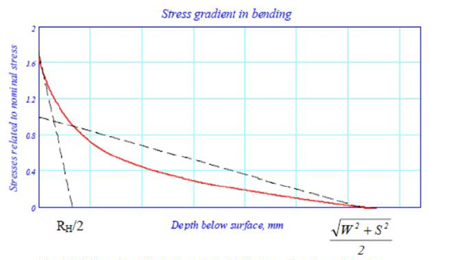

Figure 3.3.2 Bending SCF in the crankpin fillet as a function of depth
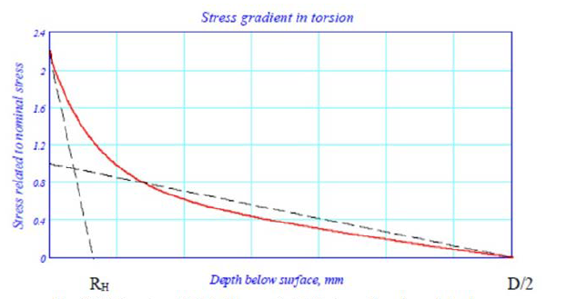

Figure 3.3.3 Torsional SCF in the crankpin fillet as a function of depth
3.2.8 If the pin is hardened only and the end of the hardened zone is closer to the fillet
than three times the maximum hardness depth, FEA should be used to determine the
actual stresses in the transition zone.