6.2.1 The fatigue strength obtained can be documented by means of full size crank tests or
by empirical methods, if these are applied to be on the safe side. If both bending
and torsion fatigue strengths have been investigated and differ from the ratio √3,
the von Mises criterion should be excluded.
6.2.2 If only bending fatigue strength has been investigated, the torsional
fatigue strength should be assessed conservatively. If the bending fatigue strength
is concluded to be x per cent above the fatigue strength of the non-peened material,
the torsional fatigue strength should not be assumed to be more than 2/3 of x per
cent above that of the non-peened material.
6.2.3 As a result of the stroke peening process, the maximum compressive residual stress is
found in the subsurface area. Therefore, depending on the fatigue testing load and
the stress gradient, it is possible to have higher working stresses at the surface
in comparison to the local fatigue strength of the surface. Because of this
phenomenon, small cracks may appear during the fatigue testing, which will not be
able to propagate in further load cycles and/or with further slight increases of the
testing load because of the profile of the compressive residual stress. Put simply,
the high compressive residual stresses below the surface ‘arrest’ small surface
cracks.
This is illustrated in Figure 3.6.1 Working and residual stresses
below the stroke-peened surface as gradient load 2. It should be noted
that straight lines 1, 2 and 3 represent different possible load stress
gradients.
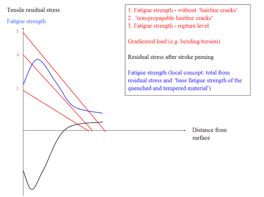
Figure 3.6.1 Working and residual stresses
below the stroke-peened surface
6.2.4 In fatigue testing with full-size crankshafts, these small “hairline
cracks” should not be considered to be the failure crack. The crack that is
technically the fatigue crack leading to failure, and that therefore shuts off the
test-bench, should be considered for determination of the failure load level. This
also applies if induction-hardened fillets are stroke-peened.
6.2.5 In order to improve the fatigue strength of induction-hardened fillets it is possible
to apply the stroke peening process in the crankshafts’ fillets after they have been
induction-hardened and tempered to the required surface hardness. If this is done,
it might be necessary to adapt the stroke peening force to the hardness of the
surface layer and not to the tensile strength of the base material. The effect on
the fatigue strength of induction hardening and stroke peening the fillets shall be
determined by a full size crankshaft test.
6.2.6 The increase in fatigue strength, which is achieved by applying stroke peening, may
be utilised in another similar crankshaft if all the following criteria are
fulfilled:
- Ball size relative to fillet radius within ±10 per cent in comparison to the
tested crankshaft;
- At least the same circumferential extension of the stroke peening;
- Angular extension of the fillet contour relative to fillet radius within ±15
per cent in comparison to the tested crankshaft and located to cover the
stress concentration during engine operation;
- Similar base material, e.g. alloyed quenched and tempered;
- Forward feed of ball of the same proportion of the radius;
- Force applied to ball proportional to base material hardness (if different);
- Force applied to ball proportional to square of ball radius.