
Section
2 Pressure components
2.1 General
2.1.1 This
Section includes requirements for calculation of hydrostatic, hydrodynamic
and impact pressures.
2.1.2 The
calculation of the impact pressures is based on the Ochi-Motter slamming
approach and is equivalent to the standard direct calculation procedure.
The values of m
0, variance of the relative
vertical motion, and m
1, variance of the relative
vertical velocity, may be derived using direct calculations. In this
case the variances are to be based on sea states as defined by the
normal design assessment environmental criteria, see
Vol 1, Pt 5, Ch 2 Environmental Conditions.
2.2 Hydrostatic pressure
2.2.1 The
hydrostatic pressure P
hys is to be taken as:
2.3 Hydrodynamic wave pressure
2.3.1 The
hydrodynamic wave pressure P
hyd is to be taken
as the greater of the pressure due to relative motion,
P
rm, and the pressure due to the pitching
motion, P
pm
2.3.2 Hydrodynamic
pressure due to relative motion P
rm is to
be taken as:
where
|
|
= |
f
type is a service type factor to be
taken as:
|
|
|
= |
1,05 for passenger
ships |
| = |
1,16 for cargo ships |
| = |
1,26 for naval ships |
| = |
1,31 for workboat ships |
|
f
z
|
= |
the vertical distribution factor |
| = |

|
|
k
z
|
= |
e
-u
|
|
u
|
= |

|
|
H
rm
|
= |
is defined in Vol 1, Pt 5, Ch 3, 2.2 Design accelerations 2.2.4
|
|
|
= |
z, z
k and T
x are defined in Vol 1, Pt 5, Ch 1, 1.4 Symbols and definitions
|
2.3.3 The
distribution of hydrodynamic pressure due to pitching motion P
pm is to be taken as:
2.3.4 The
nominal wave height limit, H
w, above the design
draft T
x is to be taken as:
2.4 Bottom impact pressure
2.4.1 If the
Complementary Rules are the Rules and Regulations for the Classification
of Ships (hereinafter referred to as the Rules for Ships) or
the Rules and Regulations for the Classification of Naval Ships (hereinafter
referred to as Rules for Naval Ships) then the bottom impact pressure
due to slamming, IP
bi is to be derived using
the method given below. This method will produce impact pressures
over the whole of the underwater plating region:

where
|
k
sl |
= |
hull form coefficient |
| = |
 for βρ ≥ 10 for βρ ≥ 10 |
| = |
28 (1–Tan (2βρ)
for βρ < 10
|
|
V
bs
|
= |
slamming velocity, in m/s, and is given by |
| = |
 for N
sl ≥ 1 for N
sl ≥ 1
|
| = |
0 for N
sl < 1
|
|
V
th
|
= |
threshold velocity for slamming, in m/s |
| = |

|
|
N
sl
|
= |
number of slams in a 3 hour period |
| = |

|
|
PR
sl
|
= |
probability of a slam |
| = |
e
-u
|
|
u
|
= |

|
|
z
wl
|
= |
distance of the centroid of the area of plating or stiffener
to the local design waterline |
| = |
z - (T
x + z
k)
|
|
m
1
|
= |
variance of the relative vertical velocity |
| = |
0,25 (ωe
f
sl
H
rm)2
|
|
m
0
|
= |
variance of the relative vertical velocity |
| = |
0,25 (f
sl
H
rm)2
|
|
ω |
= |
effective
wave frequency based on 80 per cent ship length |
| = |

|
|
ωe
|
= |
effective
encounter wave frequency |
| = |

|
|
f
sl
|
= |
probability level correction factor for relative vertical motion |
| = |
1,0 |
|
βp
|
= |
deadrise
angle, in degrees, see
Figure 5.2.1 Impact angles for slamming loads
|
|
|
= |
z, z
k, z
wl, T
x, g, V
sp and H
rm are defined in Vol 1, Pt 5, Ch 1, 1.4 Symbols and definitions
|
L
wl is defined in Vol 1, Pt 1, Ch 1, 5.2 Principal particulars.
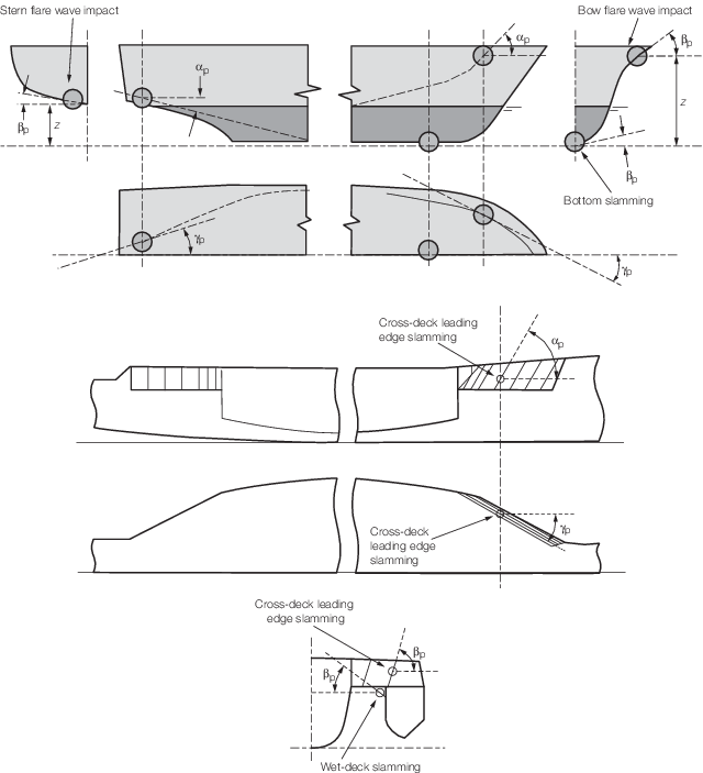
Figure 5.2.1 Impact angles for slamming loads
2.4.2 If the
Complementary Rules are the Rules and Regulations for the Classification
of Special Service Craft (hereinafter referred to as Rules
for Special Service Craft) then the bottom impact pressure due to
slamming, IP
bi, is to be derived using the
method given below. This method will produce impact pressures forward
of 0,8L from the aft end over the underwater plating
region:
where
|
f
bi
|
= |
0,09 at fwd end of L
R
|
|
f
bi
|
= |
0,18 at 0,9L
R
|
|
f
bi
|
= |
0,18 at 0,8 L
R
|
V
sp is defined in Vol 1, Pt 5, Ch 1, 1.4 Symbols and definitions.
2.5 Wave impact pressure above waterline
2.5.1 If the
Complementary Rules are the Rules for Ships or the Rules for Naval
Ships then the wave impact pressure above the waterline due to slamming, IP
wi, is to be derived using the method given below.
This method will produce impact pressures for the following areas:
- Over the fore end side and bow structure above the waterline up
to the deck at side
- Over the wet-deck structure of the cross-deck
- Over the leading edge structure of the cross deck
- Over the after body in way of a flat counter stern which is close
to the waterline

where
|
k
wi
|
= |
hull form coefficient |
| = |
 for βp ≥ 10 for βp ≥ 10
|
| = |
28 (1 – Tan (2βp) for
βp < 10
|
|
V
wi
|
= |
slamming velocity, in m/s and is given by |
| = |
 for N
wi ≥ 1 for N
wi ≥ 1
|
| = |
0 for N
wi < 1
|
|
V
thwi
|
= |
threshold velocity for slamming, in m/s |
| = |

|
|
N
wi
|
= |
Number of slams in a three hour period |
| = |

|
|
PR
wi
|
= |
probability of a slam and is given by |
| = |
e
–u
|
|
u
|
= |

|
|
k
rv
|
= |
hull form shape coefficient for impact due to forward speed |
| = |
 for αp ≤ 80 for αp ≤ 80
|
| = |
28 [1 – tan (2 (90 – αp))]
for αp > 80
|
|
H
rv
|
= |
relative wave heading coefficient |
| = |
1,0 for γp ≥ 45
|
| = |
cos (45 – γp) for γp < 45 and ≥ 0
|
| = |
0 for γp < 0
|
|
V
rv
|
= |
relative forward speed, in m/s |
| = |
0,515V
sp sin (γp)
|
|
αp
|
= |
buttock
angle, in degrees, see
Figure 5.2.1 Impact angles for slamming loads
|
|
βp
|
= |
flare
angle, in degrees, see
Figure 5.2.1 Impact angles for slamming loads
|
|
γp
|
= |
waterline
angle, in degrees, see
Figure 5.2.1 Impact angles for slamming loads
|
|
|
= |
m1 and m0 are defined in Vol 1, Pt 5, Ch 5, 2.4 Bottom impact pressure 2.4.1
|
|
|
= |
z
wl and V
sp are
defined in Vol 1, Pt 5, Ch 1, 1.4 Symbols and definitions.
|
2.5.2 The
flare angle, βp, is to be decreased by 10° to allow
for the effects of roll motion on the above waterline impact pressures.
2.5.3 Where
only two angles are known, then the third may be obtained by the following
expression:
2.5.4 If the
area of plating under consideration has a waterline angle which is
re-entrant or decreasing, e.g. in the stern region, then the relative
wave heading coefficient, H
rv and the speed V
sp used in the derivation of H
rm are
to be taken as zero.
2.5.5 If the
Complementary Rules are the Rules for Special Service Craft then the
impact pressure above the waterline, IP
wi,
is to be derived using the methods given below:
For bow flare slamming:
where
|
Γ |
= |

|
|
IP
wi
|
= |

|
|
|
= |
IP
wi = P
des at
0,8L
R
|
These formulae give pressures to be applied at the design waterline.
At the weather deck the pressure is to be taken as 0,4IP
wi and intermediate values determined by interpolation.
For wet-deck slamming:
where
|
f
imp
|
= |
1/3 for the leading edge of the wet-deck |
| = |
1/6 for the underside of the wet-deck |
|
k
f
|
= |
is a longitudinal distribution factor |
| = |
2,0 for the forward quarter of the wet-deck |
| = |
1,0 elsewhere |
|
V
R
|
= |
is the relative vertical speed of the craft at impact, in knots.
If this value is unknown, then the following equation is to be used: |
|
V
R
|
= |

|
|
G
A
|
= |
Air Gap between underside of wet-deck and design waterline |
|
H
|
= |
is
minimum significant waveheight |
|
|
= |
For G1 ships H = 0,6
|
|
|
= |
For G2 ships H = 1,0
|
|
|
= |
For G3 ships H = 2,0
|
|
|
= |
For G4, G5 and G6 ships H = 4,0
|
|
V
sp
|
= |
is as defined in Vol 1, Pt 5, Ch 1, 1.4 Symbols and definitions
|
|
V
|
= |
is
maximum service speed, in knots |
|
P
des
|
= |
is given in Vol 1, Pt 5, Ch 5, 3.2 Combined pressure.
|
2.6 Minimum weather deck pressure
2.6.1 The
minimum weather deck pressure, P
d, is to be
taken as:
|